English
 日本語
日本語 한국어
한국어 Россия
  Français
 España
 عرب .
عرب .  Português
 Deutsch
 भारत
भारत Нидерланды

- Recommended news
-
System composition of CNC horizontal machining center
2024-06-18
-
A method to solve the problem of spindle shaking in CNC lathes
2024-06-15
-
In which industry is the most widely used CNC vertical lathe?
2024-06-04
-
How to clamp the workpiece on a CNC vertical lathe?
2024-05-29
-
CNC milling machine machining center commonly used accessories
2024-05-25
-
Steps for adjusting the turret of a CNC vertical lathe
2024-05-22
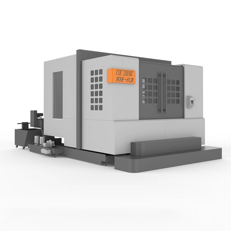
Automated horizontal machining center
An automated horizontal machining center is a mechanical equipment used for automated processing, usually in a horizontal position, where the workpiece is placed horizontally....


An automated horizontal machining center is a mechanical equipment used for automated processing, usually in a horizontal position, where the workpiece is placed horizontally. Compared with vertical machining centers, automated horizontal machining centers have different structures and processing characteristics. Here is some important information about automated horizontal machining centers:
1. Working principle: The automated horizontal machining center controls each axial movement through the CNC system to drive the tool or workpiece for processing. The workpiece of the automated horizontal machining center is processed in a horizontal position, and gravity has less impact on the workpiece and tool during the processing.
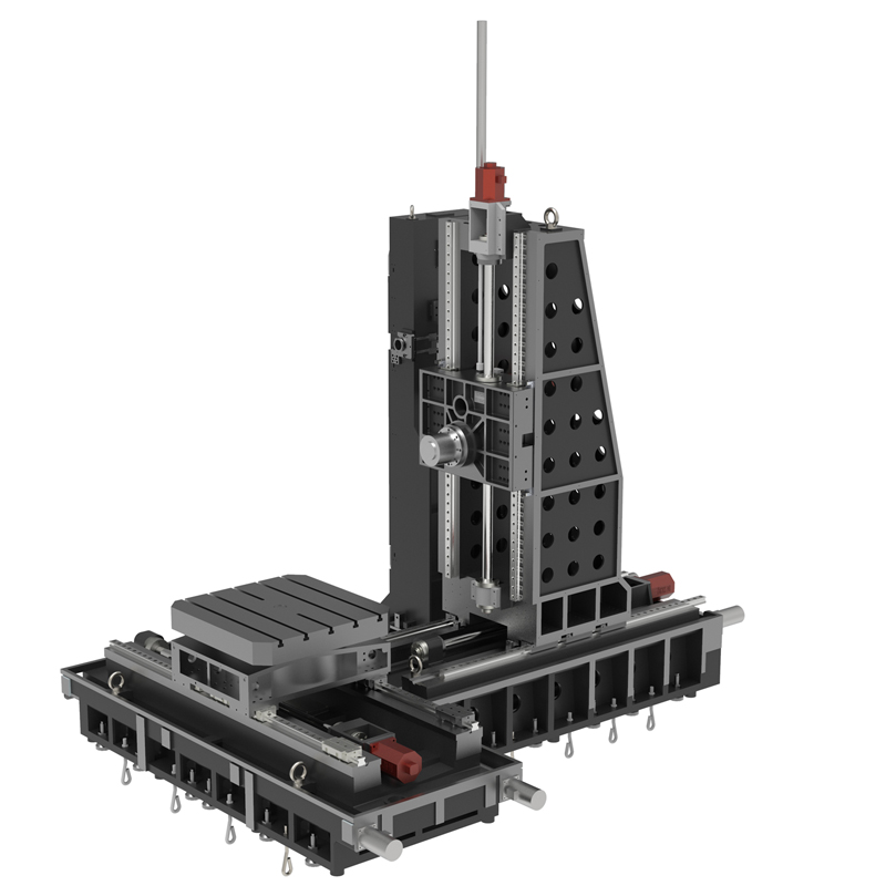
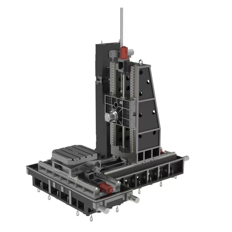
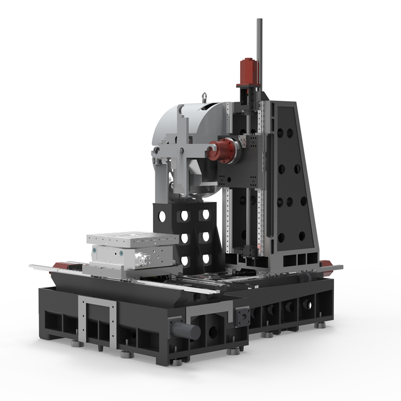
2. Equipment composition: An automated horizontal machining center usually consists of a machine tool body, a CNC system, a tool magazine/tool changing device, a workpiece clamping device, an automated feeding device, a lubrication system, a cooling system and other components. The automatic feeding device can realize automatic loading and unloading of workpieces and improve production efficiency.
3. Processing capabilities: The automated horizontal machining center has multi-axis control capabilities and is suitable for processing complex parts, such as curved surface processing, hole processing, thread processing, etc. Since the workpiece of the automated horizontal machining center is placed horizontally, chips are easily removed during processing, and it is suitable for machining situations that require high cutting fluids.
4. Advantages: Compared with vertical machining centers, automated horizontal machining centers have a more stable workpiece clamping method and are suitable for processing large and heavy parts. Since the workpiece of the automated horizontal machining center is placed horizontally, it has less impact on vibration and deformation during the machining process, which can improve machining accuracy and surface quality.
5. Application fields: Automated horizontal machining centers are widely used in automobile manufacturing, aerospace, mold manufacturing, casting processing and other industries. They are especially suitable for processing large and heavy parts or occasions that require high processing accuracy.
Generally speaking, the automated horizontal machining center is an efficient, stable, and precise processing equipment that can improve production efficiency, reduce costs, and ensure product quality. It is one of the indispensable and important equipment in modern manufacturing.
| Specifications/model | Unit | WH50A | WH50B | WH63A | WH63B | WH75A | WH75B | WH80A | WH80B | WH100A | WH100B |
| Work content | |||||||||||
| Work surface size (optional) | MM | 500×500 | 500×500 | 630×630 | 630×630 | 750×750 | 750×750 | 800×800 | 800×800 | 1000×1000 | 1000×1000 |
| Workbench indexing (standard) | °C | 0.001 | 0.001 | 1 | 1 | 1 | 1 | 1 | 1 | 1 | 1 |
| Customized workbench (optional) | °C | 1/5/90 | 1/5/90 | 0.001/5/90 | 0.001/5/90 | 0.001/5/90 | 0.001/5/90 | 0.001/5/90 | 0.001/5/90 | 0.001/5/90 | 0.001/5/90 |
| Maximum rotation diameter of worktable | MM | 700 | 700 | 1300 | 1300 | 1400 | 1400 | 1600 | 1600 | 1900 | 1900 |
| X-axis travel | MM | 700 | 700 | 1050 | 1050 | 1300 | 1300 | 1300 | 1300 | 1600 | 1600 |
| Y-axis travel (headstock moves up and down) | MM | 600 | 600 | 770 | 770 | 1000 | 1000 | 1000 | 1000 | 1200 | 1200 |
| Z-axis travel | MM | 600 | 600 | 900 | 900 | 950 | 950 | 1000 | 1000 | 1200 | 1200 |
| Distance from spindle center to worktable | MM | 110-190 | 110-190 | 120-890 | 120-890 | 120-1120 | 120-1120 | 120-1120 | 120-1120 | 120-1320 | 120-1320 |
| Distance from spindle end face to worktable center | MM | 200-800 | 200-800 | 170-1070 | 170-1070 | 250-1200 | 250-1200 | 300-1300 | 300-1300 | 400-1600 | 400-1600 |
| Workbench (slot width*number of slots) | MM | 3-14 | 3-14 | 5-22 | 5-22 | 5-22 | 5-22 | 9-24 | 9-24 | 9-24 | 9-24 |
| Threaded hole (optional) | MM | 24-M14 | 24-M14 | 24-M16 | 24-M16 | 24-M16 | 24-M16 | 24-M16 | 24-M16 | 24-M16 | 24-M16 |
| Workbench load-bearing capacity (per block) | KG | 600 | 600 | 1200 | 1200 | 1700 | 1700 | 2100 | 2100 | 3200 | 3200 |
| Spindle and spindle box specifications | |||||||||||
| Spindle taper hole | ISO | BT50-150 | BT50-150 | BT50-190 | BT50-190 | BT50-190 | BT50-190 | BT50-190 | BT50-190 | BT50-190 | BT50-190 |
| Spindle belt speed (standard/optional) | RPM | 6000 | 6000 | 4000, 6000 | 4000, 6000 | 4000, 6000 | 4000, 6000 | 4000, 6000 | 4000, 6000 | 4000, 6000 | 4000, 6000 |
| Transmission gearbox ratio (optional) | N | / | / | 1:1/1:4 | 1:1/1:4 | 1:1/1:4 | 1:1/1:4 | 1:1/1:4 | 1:1/1:4 | 1:1/1:4 | 1:1/1:4 |
| Electric spindle HSK (optional) | HSK | A63 | A63 | A100 | A100 | A100 | A100 | A100 | A100 | A100 | A100 |
| Electric spindle speed | RPM | 18000 | 18000 | 15000 | 15000 | 15000 | 15000 | 15000 | 15000 | 15000 | 15000 |
| Feeding system | |||||||||||
| Shaft Ball Screw Specifications | MM | 40/40/40 | 40/40/40 | 40/40/50 | 40/40/50 | 50/50/50 | 50/50/50 | 50/50/50 | 50/50/50 | 63/63/63 | 63/63/63 |
| X/Y/Z axis rapid movement speed | M/MIN | 32/24/24 | 32/24/24 | 24/24/20 | 24/24/20 | 24/24/20 | 24/24/20 | 24/24/20 | 24/24/20 | 16/16/12 | 16/16/12 |
| B-axis rapid movement speed | M/MIN | B:15 | B:15 | B:10 | B:10 | B:10 | B:10 | B:10 | B:10 | B:10 | B:10 |
| X/Y/Z axis rail specifications | MM | Roller 45/45/45 | Roller 45/45/45 | Roller 55/55/55 | Roller 55/55/55 | Roller 55/55/55 | Roller 55/55/55 | Roller 55/55/55 | Roller 55/55/55 | Roller 55/55/55 | Roller 55/55/55 |
| Motor connection method | / | Direct | Direct | Direct | Direct | Direct | Direct | Direct | Direct | Direct | Direct |
| Main motor parameters | KW | 11 | 11 | 18.5 | 18.5 | twenty two | twenty two | twenty two | twenty two | twenty two | twenty two |
| X/Y/Z axis motor power | NM | 22/22/22B | 22/22/22B | 30/40/30B | 30/40/30B | 30/40/30B | 30/40/30B | 40/40/30B | 40/40/30B | 40/40/30B | 40/40/30B |
| B-axis motor power | NM | B:8 | B:8 | B:12 | B:12 | B:22 | B:22 | B:22 | B:22 | B:30 | B:30 |
| Axis positioning accuracy | MM | 0.01 | 0.01 | 0.012 | 0.012 | 0.012 | 0.012 | 0.013 | 0.013 | 0.015 | 0.015 |
| Axis item repeat positioning accuracy | MM | 0.005 | 0.005 | 0.005 | 0.005 | 0.005 | 0.005 | 0.006 | 0.006 | 0.006 | 0.006 |
| BPositioning accuracy | SEC | 10" | 10" | 10" | 10" | 10" | 10" | 10" | 10" | 10" | 10" |
| B Repeat positioning accuracy | SEC | 3" | 3" | 3" | 3" | 3" | 3" | 3" | 3" | 3" | 3" |
| Minimum move value | MM | 0.001 | 0.001 | 0.001 | 0.001 | 0.001 | 0.001 | 0.001 | 0.001 | 0.001 | 0.001 |
| Oil and gas pressure system | |||||||||||
| air pressure | KG/MM | 6.5 | 6.5 | 6.5 | 6.5 | 6.5 | 6.5 | 6.5 | 6.5 | 6.5 | 6.5 |
| coolant capacity | L | 450 | 450 | 550 | 550 | 600 | 600 | 650 | 650 | 750 | 750 |
| Lubricating oil capacity L | L | 4 | 4 | 4 | 4 | 4 | 4 | 4 | 4 | 4 | 4 |
| Total power capacity | KVA | 35 | 37 | 40 | 42 | 45 | 47 | 45 | 47 | 45 | 45 |
| Toolholder/Tool Magazine System (specify when ordering) | |||||||||||
| Tool magazine structure | / | Disc knife arm type | Disc knife arm type | Disc knife arm type | Disc knife arm type | Disc knife arm type | Disc knife arm type | Disc knife arm type | Disc knife arm type | Disc knife arm type | Disc knife arm type |
| Number of tool magazines (optional) | T | 24, 32, 40 | 24, 32, 40 | 24, 32, 40 | 24, 32, 40 | 24, 32, 40 | 24, 32, 40 | 24, 32, 40 | 24, 32, 40 | 24, 32, 40 | 24, 32, 40 |
| Knife inventory structure (optional) | / | Chain plate type | Chain plate type | Chain plate type | Chain plate type | Chain plate type | Chain plate type | Chain plate type | Chain plate type | Chain plate type | Chain plate type |
| Number of tool magazines | T | 40/50/60/80 | 40/50/60/80 | 40/50/60/80 | 40/50/60/80 | 40/50/60/80 | 40/50/60/80 | 40/50/60/80 | 40/50/60/80 | 40/50/60/80 | 40/50/60/80 |
| Tool changing time T | SEC | 3.8/5.2 | 3.8/5.2 | 3.8/5.2 | 3.8/5.2 | 3.8/5.2 | 3.8/5.2 | 3.8/5.2 | 3.8/5.2 | 3.8/5.2 | 3.8/5.2 |
| Maximum tool weight (optional) KGS | 8/10 | 8/10 | 15/18 | 15/18 | 15/18 | 15/18 | 15/18 | 15/18 | 15/18 | 15/18 | 15/18 |
| Maximum tool/adjacent tool clearance diameter | MM | φ110/φ200 | φ110/φ200 | φ110/φ200 | φ110/φ200 | φ110/φ200 | φ110/φ200 | φ110/φ200 | φ110/φ200 | φ110/φ200 | φ110/φ200 |
| Form factor | |||||||||||
| Weight approx. | KG | 5.5 | 6.5 | 12.5 | 15.5 | 14 | 17 | 18.5 | 22.5 | 19.5 | 19.5 |
| Machine length | MM | 3500 | 4800 | 4800 | 6100 | 5100 | 7000 | 5350 | 7200 | 5300 | 5300 |
| Machine width | MM | 3100 | 3300 | 3400 | 4150 | 4200 | 5500 | 4200 | 5680 | 4500 | 4500 |
| Machine height (maximum) | MM | 3200 | 3200 | 3400 | 4550 | 4400 | 4400 | 4400 | 4400 | 4700 | 4700 |
| Machine tool structure | / | Positive T shape | Positive T shape | Inverted T shape | Inverted T shape | Inverted T shape | Inverted T shape | Inverted T shape | Inverted T shape | Inverted T shape | Inverted T shape |
| Chip removal method | / | Twin screw rear row | Twin screw rear row | Twin screw single chain plate | Twin screw single chain plate | Twin screw single chain plate | Twin screw single chain plate | Twin screw single chain plate | Twin screw single chain plate | Twin screw single chain plate | Twin screw single chain plate |