- Recommended news
-
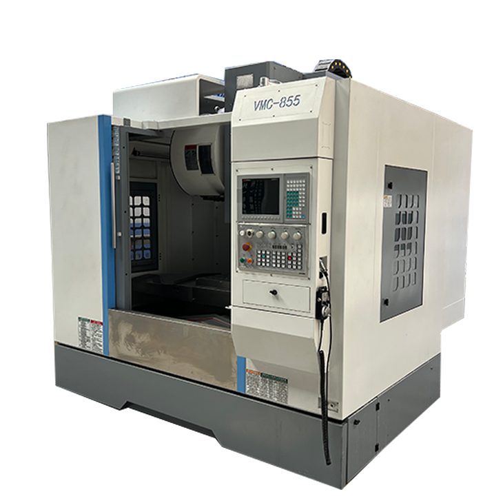
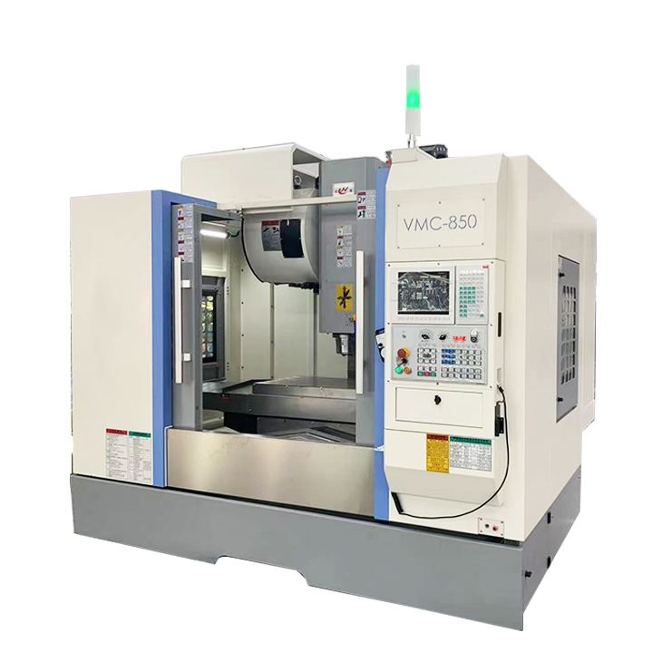
System composition of CNC horizontal machining center
2024-06-18
-
A method to solve the problem of spindle shaking in CNC lathes
2024-06-15
-
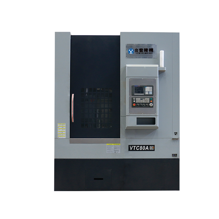
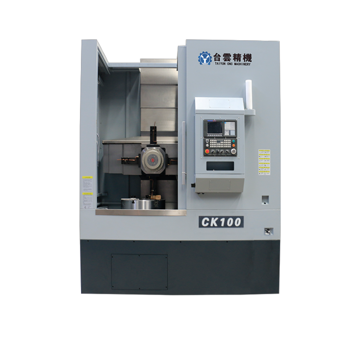
In which industry is the most widely used CNC vertical lathe?
2024-06-04
-
How to clamp the workpiece on a CNC vertical lathe?
2024-05-29
-
CNC milling machine machining center commonly used accessories
2024-05-25
-
Steps for adjusting the turret of a CNC vertical lathe
2024-05-22
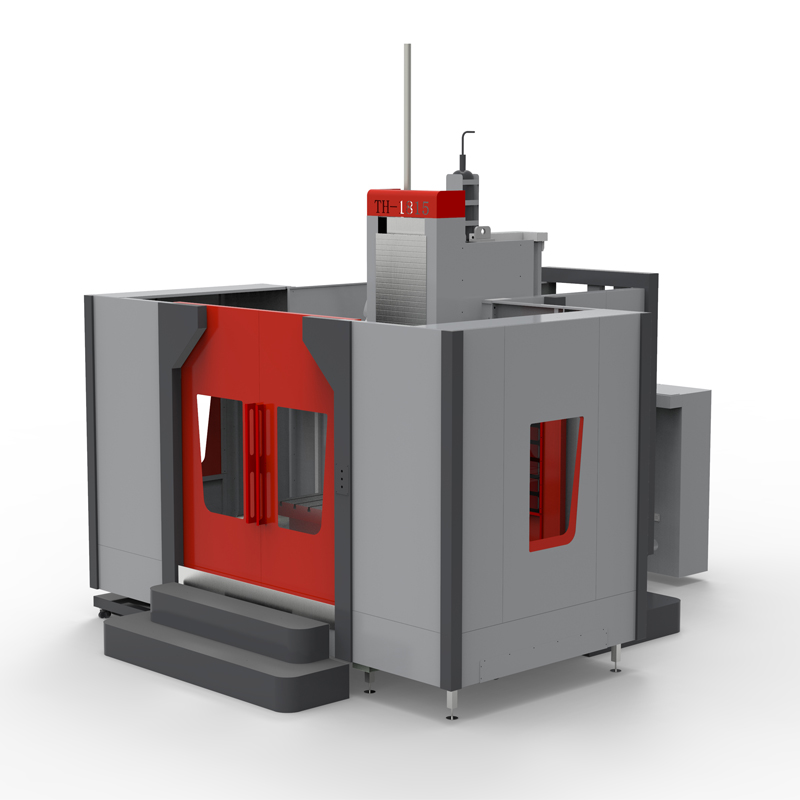
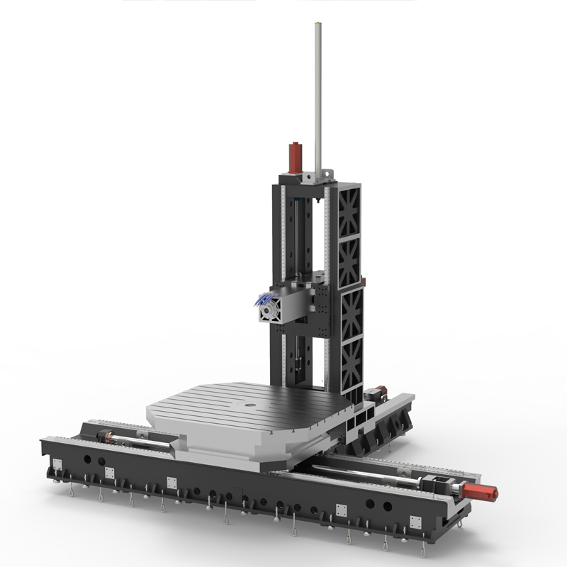
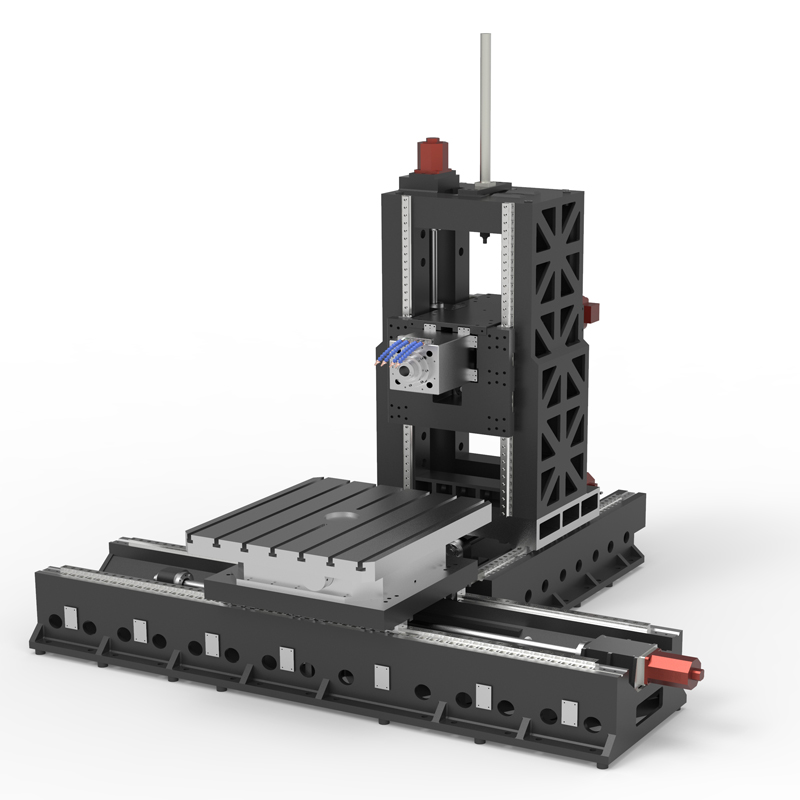
Horizontal machining center boring and milling machine
Horizontal machining center boring and milling machine is a type of machine tool used for processing large workpieces, which has the following characteristics and advantages:...
Horizontal machining center boring and milling machine is a type of machine tool used for processing large workpieces, which has the following characteristics and advantages:
1. Horizontal layout: The workpiece of the horizontal machining center boring and milling machine is placed horizontally on the machine tool workbench, and the tool moves vertically, making it convenient for workpiece clamping and processing operations, suitable for processing large workpieces.
2. Multifunctional machining: The horizontal machining center boring and milling machine has various machining functions such as boring, milling, drilling, etc. It can complete various machining processes of complex workpieces, improve machining efficiency and production capacity.
3. High precision machining: The horizontal machining center boring and milling machine is equipped with a high-precision CNC system and high-quality cutting tools, which can achieve high-precision machining and meet the requirements of the workpiece for size and surface quality.
4. Automated processing: The horizontal machining center boring and milling machine supports automated processing functions, such as automatic tool changing, automatic measurement, automatic compensation, etc., which can improve production efficiency and processing accuracy.
5. Large stroke and large load capacity: Horizontal machining center boring and milling machines have large machining stroke and load capacity, suitable for the processing needs of large workpieces, and can meet the processing requirements of workpieces of different sizes.
6. Ergonomic design: The ergonomic design of the horizontal machining center boring and milling machine makes the operation more user-friendly, such as a friendly human-machine interface, convenient operation, and complete safety protection facilities, improving the comfort and safety of the operator's work.
Horizontal machining center boring and milling machines are widely used in the processing of large workpieces in aerospace, automotive, shipbuilding, railway and other fields. They have the advantages of wide processing range, high processing efficiency, and high processing accuracy, and are one of the important processing equipment in modern manufacturing industry.
| Specifications/model | Unit | WB14B/C/D | WB18B/C/D | WB24B/C/D |
| Workbench specifications | ||||
| Rotary work surface dimensions | MM | 1400×1200 | 1800×1600 | 2400×2200 |
| Turntable structure (standard) | ℃ | 0.001 | 0.001 | 0.001 |
| Turntable structure (optional) | ℃ | 1/5/90 | 1/5/90 | 1/5/90 |
| Turntable load-bearing | T | 7 | 12 | 20 |
| Machine tool mechanism | / | Inverted T shape | Inverted T shape | Inverted T shape |
| Worktable left and right travel X mark/select | MM | 2000/2500 | 2500/3000 | 3000/4000 |
| Spindle box upper and lower stroke Y mark/select MM | 1000/1500 | 1500/2000 | 2000/2500 | |
| Column front and rear travel Z1 | MM | 1000 | 1000 | 1500 |
| Type B square ram front and rear travel Z2 | MM | 600 | 600 | 600 |
| Square ram specifications | MM | 360*360 | 360*360 | 360*360 |
| Maximum spindle speed/optional | RPM | 4000/6000 | 4000/6000 | 4000/6000 |
| C type boring bar front and rear travel Z2 | MM | 600 | 600 | 600 |
| Boring bar specifications | MM | 130 | 130 | 130 |
| Maximum spindle speed/optional | RPM | 1200/2000 | 1200/2000 | 1200/2000 |
| Distance from spindle end face to table center | MM | 200-1400 | 500-1700 | 600-2300 |
| Distance from spindle center to table surface | MM | 100-11/160000 | 100-1600/2100 | 100-2100/2600 |
| Workbench T-slot (slot width * number of slots) | / | 24*7 | 24*9 | 24*11 |
| Spindle content | ||||
| Spindle model/installation dimensions | MM | BT50/190 | BT50/190 | BT50/190 |
| Spindle motor | KW | 22KW | 22KW | 22KW |
| Maximum spindle speed/optional | RPM | 3000/4000 | 3000/4000 | 3000/4000 |
| Spindle drive | / | Variable speed gear transmission | Variable speed gear transmission | Variable speed gear transmission |
| Axis item content | ||||
| X-axis guide rail specifications/quantity | MM/N | Roller 55/2 | Roller 55/2 | Roller 55/2 |
| Y-axis guide rail specifications/quantity | MM/N | Roller 45/4 | Roller 45/4 | Roller 45/4 |
| Z-axis guide rail specifications/quantity | MM/N | Roller 55/2+hard rail | Roller 55/2+hard rail | Roller 55/2+hard rail |
| Three-axis ball screw specifications | MM | 63, 50, 63 | 63, 50, 63 | 63, 50, 63 |
| Square ram or boring bar ball screw specifications | MM | 40 | 40 | 40 |
| XY fast movement speed | M/MIN | 12, 12 | 12, 12 | 12, 12 |
| Z1/Z2 speed moving speed | M/MIN | 12, 20 | 12, 20 | 12, 20 |
| Three-axis motor connection method | / | direct connection | Reducer + direct connection | Reducer + direct connection |
| X, Y brake power | NM | 40, 40B | 40, 40B | 40, 40B |
| Z1, Z2 power | NM | 40, 22 | 40, 22 | 40, 22 |
| Spindle box balancing system | / | Nitrogen balance | Nitrogen balance | Nitrogen balance |
| air pressure | KG/MM | 6.5 | 6.5 | 6.5 |
| coolant capacity | L | 450 | 450 | 450 |
| Lubricating oil capacity | L | 4 | 4 | 4 |
| Oil and gas pressure system | ||||
| battery capacity | KW | 55 | 55 | 55 |
| Voltage floating | VAC | 380±5% | 380±5% | 380±5% |
| Phase | PHASE | 3 boxes 5 lines | 3 boxes 5 lines | 3 boxes 5 lines |
| air pressure | KG | 6.5-8 | 6.5-8 | 6.5-8 |
| Form factor | ||||
| Machine weight (approx.) | T | 22/26 | 26/30 | 33/37 |
| Machine length (front and rear) markings | MM | 4000 | 4500 | 5000 |
| Machine width (left and right) mark | MM | 6000 | 7000 | 8000 |
| Machine height (maximum) mark | MM | 4500 | 4500 | 4500 |
| Chip removal method | / | Twin screw/chain plate type | Twin screw/chain plate type | Twin screw/chain plate type |

 English
 日本語
日本語 한국어
한국어 Россия
  Français
 España
 عرب .
عرب .  Português
 Deutsch
 भारत
भारत Нидерланды
