English
 日本語
日本語 한국어
한국어 Россия
  Français
 España
 عرب .
عرب .  Português
 Deutsch
 भारत
भारत Нидерланды

- Recommended news
-
System composition of CNC horizontal machining center
2024-06-18
-
A method to solve the problem of spindle shaking in CNC lathes
2024-06-15
-
In which industry is the most widely used CNC vertical lathe?
2024-06-04
-
How to clamp the workpiece on a CNC vertical lathe?
2024-05-29
-
CNC milling machine machining center commonly used accessories
2024-05-25
-
Steps for adjusting the turret of a CNC vertical lathe
2024-05-22
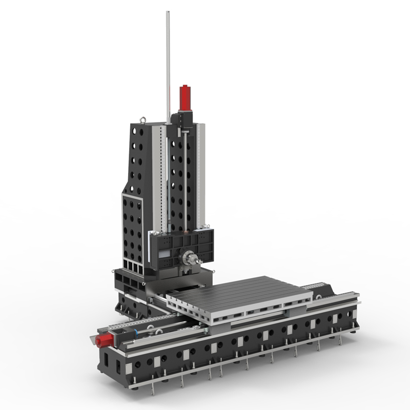
Inverted T type horizontal machining center
"Inverted T" horizontal machining center usually refers to a horizontal machining center with a "T" shaped worktable structure....


"Inverted T" horizontal machining center usually refers to a horizontal machining center with a "T" shaped worktable structure. The worktable of the "inverted T-type" horizontal machining center has an inverted T shape, which makes the workpiece clamping more stable and can also accommodate large workpieces. Horizontal machining centers of this structure usually have the following features and advantages:
1. Stability: The inverted T-shaped worktable structure makes the workpiece clamping more stable, helping to improve processing accuracy and surface quality.
2. Adaptability: The inverted T-shaped workbench can accommodate large workpieces and is suitable for occasions where large-sized workpieces need to be processed.
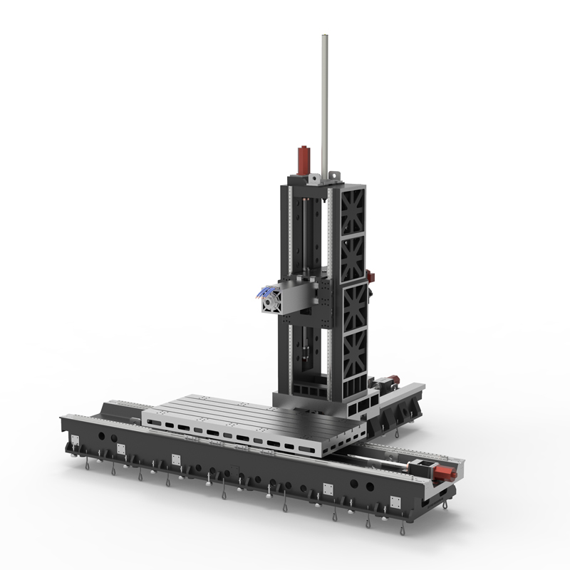
3. Multi-station processing: The inverted T-shaped workbench usually has multiple workpiece clamping positions, which can process multiple workpieces at the same time to improve production efficiency.
4. Flexibility: Horizontal machining centers with this structure usually have a large processing range and workbench size, can process workpieces of various shapes and sizes, and have strong processing flexibility.
5. Automation: Horizontal machining centers with an inverted T-shaped table structure can usually be equipped with automated equipment, such as automatic tool changing systems, automatic workpiece clamping systems, etc., to achieve automated processing and improve production efficiency.
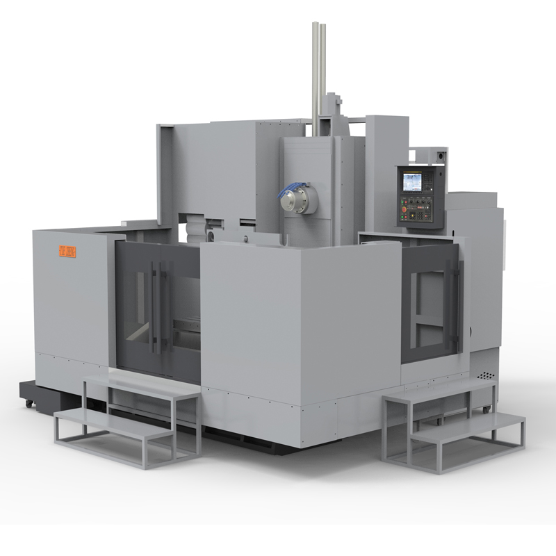
In general, the horizontal machining center with an inverted T-shaped table structure has the advantages of high stability, strong adaptability, multi-station processing, flexibility and automation, and is suitable for applications that require high processing accuracy, large workpiece size or Application scenarios requiring mass production.
| Specifications/Models | Unit | WY10 | WY15 | WY20 | WY25 | WY30 | WY40 |
| Work content | |||||||
| Work surface size | MM | 1200×1600 | 1700×800 | 2000×1200 | 2500×1400 | 3000×1400 | 4000×1400 |
| X-axis travel | MM | 1100 | 1600 | 2100 | 2600 | 3100 | 4200 |
| Y-axis spindle box up and down travel (standard/optional) | MM | 700/900 | 700/900 | 1000/1500 | 1000/1500 | 1500/2000 | 1500/2000 |
| Z-axis column front and rear travel (standard, optional) | MM | 800 | 800/1200 | 800/1200 | 800/1200 | 800/1200 | 800/1200 |
| Distance from spindle center to worktable | MM | 120-890 | 120-1120 | 120-1320 | 120-1820 | 120-1820 | 120-2120 |
| Distance from spindle end face to worktable center | MM | 130-1030 | 200-1200 | 400-1600 | 500-1700 | 500-1700 | 700-1700 |
| Workbench slot width + T slot | MM | 5-22 | 9-28 | 9-28 | 11-28 | 11-28 | 11-28 |
| Workbench load-bearing | KG | 1200 | 2500 | 3000 | 6000 | 10000 | 14000 |
| Spindle and spindle specifications | |||||||
| Spindle taper hole | ISO | BT50-190 | BT50-190 | BT50-190 | BT50-190 | BT50-190 | BT50-190 |
| Spindle speed | RPM | 4000/6000 | 4000/6000 | 4000/6000 | 4000/6000 | 4000/6000 | 4000/6000 |
| Type A boring bar specification diameter (optional) | MM | / | 110 | 110 | 130 | 130 | 130 |
| Boring bar stroke Z1 (optional) | MM | / | 550 | 550 | 550 | 550 | 550 |
| Type B square ram specifications square type (optional) | MM | / | / | 320 | 320 | 320 | 320 |
| Square ram stroke Z2 (optional) | MM | / | / | 600 | 600 | 600 | 600 |
| T-shaped workbench (slot width * number of slots) | / | 28*300 | / | 28*300 | 28*300 | 28*300 | 28*300 |
| Feeding system | |||||||
| Shaft Ball Screw Specifications | MM | 40/40/50 | 50/50/50 | 63/50/50 | 63/50/50 | 63/50/50 | 80/63/63 |
| XYZ axis rapid movement speed | M/MIN | 32.32.32 | 32.32.32 | 24.24.24 | 24.24.24 | 20.24.24 | 20.24.24 |
| X/Z axis wire gauge specifications | MM | Roller 55/55 | Roller 55/55 | Roller 55/55 | Roller 55/55 | Roller 55/55 | Roller 55/55 |
| Y-axis wire gauge specifications | MM | Roller 55 | Roller 55 | Roller 45*4 | Roller 45*4 | Roller 45*4 | Roller 45*4 |
| Motor connection method | / | Direct | Direct | Direct connection + reducer | Direct connection + reducer | Direct connection + reducer | Direct connection + reducer |
| Main motor parameter marking/selection | KW | 22/+reducer | 22/+reducer | 22/+reducer | 22/+reducer | 22/+reducer | 22/+reducer |
| Axis positioning accuracy | MM | ±0.005 | ±0.005 | ±0.005 | ±0.005 | ±0.005 | ±0.005 |
| Axis item repeat positioning accuracy | MM | ±0.003 | ±0.003 | ±0.003 | ±0.003 | ±0.003 | ±0.003 |
| Minimum move value | MM | 0.001 | 0.001 | 0.001 | 0.001 | 0.001 | 0.001 |
| Oil and gas pressure system | |||||||
| Spindle box balancing system (vertical installation) | / | gas balance | gas balance | gas balance | gas balance | gas balance | gas balance |
| air pressure | KG/MM | 6.5 | 6.5 | 6.5 | 6.5 | 6.5 | 6.5 |
| coolant capacity | L | 550 | 550 | 550 | 550 | 550 | 550 |
| Lubricating oil capacity L | L | 4 | 4 | 4 | 4 | 4 | 4 |
| Toolholder/Tool Magazine System (specify when ordering) | |||||||
| Tool magazine structure | / | Disc knife arm type | Disc knife arm type | Disc knife arm type | Disc knife arm type | Disc knife arm type | Disc knife arm type |
| Number of tool magazines (optional) | T | 24/32 | 24/32 | 24/32 | 24/32 | 24/32 | 24/32 |
| Knife inventory structure (optional) | / | Chain plate type tool magazine | Chain plate type tool magazine | Chain plate type tool magazine | Chain plate type tool magazine | Chain plate type tool magazine | Chain plate type tool magazine |
| Number of tool magazines | T | 40/50/60/80 | 40/50/60/80 | 40/50/60/80 | 40/50/60/80 | 40/50/60/80 | 40/50/60/80 |
| Tool changing time | MM | 5.2 | 5.2 | 5.2 | 5.2 | 5.2 | 5.2 |
| Maximum tool weight | KGS | 18 | 18 | 18 | 18 | 18 | 18 |
| Form factor | |||||||
| Weight approx. | T | 9 | 13/15 | 16/18 | 22/24 | 24/26 | 32/34 |
| Machine width | MM | 3000 | 4000 | 5000 | 6500 | 7500 | 9700 |
| Machine length | MM | 4500 | 5500 | 5800 | 6300 | 6300 | 7300 |
| Machine height (maximum) | MM | 4100 | 4300 | 5000 | 5500 | 5500 | 6000 |
| Machine tool mechanism | / | Inverted T shape | Inverted T shape | Inverted T shape | Inverted T shape | Inverted T shape | Inverted T shape |
| Chip removal method | / | Twin screw + chain plate | Twin screw + chain plate | Twin screw + chain plate | Twin screw + chain plate | Twin screw + chain plate | Twin screw + chain plate |