English
 日本語
日本語 한국어
한국어 Россия
  Français
 España
 عرب .
عرب .  Português
 Deutsch
 भारत
भारत Нидерланды

- Recommended news
-
System composition of CNC horizontal machining center
2024-06-18
-
A method to solve the problem of spindle shaking in CNC lathes
2024-06-15
-
In which industry is the most widely used CNC vertical lathe?
2024-06-04
-
How to clamp the workpiece on a CNC vertical lathe?
2024-05-29
-
CNC milling machine machining center commonly used accessories
2024-05-25
-
Steps for adjusting the turret of a CNC vertical lathe
2024-05-22

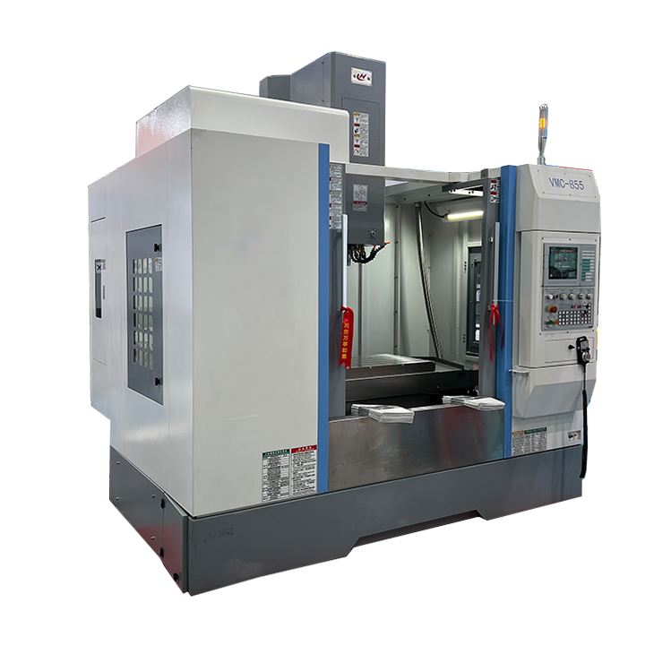
CNC machining center is not easy to deform
CNC machining centers usually use a solid body structure and a high-precision guide rail system to ensure that deformation is minimized during the machining process....


CNC machining centers usually use a solid body structure and a high-precision guide rail system to ensure that deformation is minimized during the machining process. The following are some factors that cause CNC machining centers to be less susceptible to deformation:
1. Machine tool structure design: CNC machining centers usually adopt stable cast iron or steel structures with high strength and stability. This structural design can provide good rigidity and stability when the machine tool is running, reducing the possibility of deformation.
2. High-precision guide rail system: CNC machining centers use high-precision ball screws and linear guide systems. These CNC machining center systems have high rigidity and repeatable positioning accuracy, and can reduce vibration and deformation during the processing process.
3. Temperature control: Some CNC machining centers are equipped with temperature control systems, which can control the temperature of the machine tool during the machining process and reduce the impact of thermal deformation on machining accuracy.
4. Processing parameter optimization: By optimizing processing parameters, such as cutting speed, feed speed and cutting depth, CNC machining centers can reduce the heat and cutting force generated during processing, thereby reducing the possibility of machine tool deformation.
5. Stable working environment: Keeping the working environment around the CNC machining center stable, such as temperature, humidity and vibration, can reduce the impact of external factors on the machine tool, thereby reducing the risk of deformation.
Although advancements in the design and technology of CNC machining centers have made them less susceptible to deformation during processing, reasonable use and regular maintenance are still required to ensure continued and stable performance and accuracy.
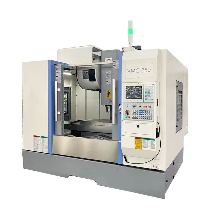
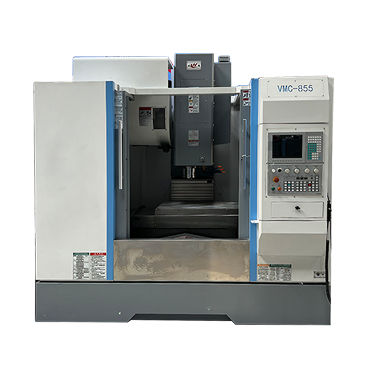
| Specifications | unit | VMC650 | VMC855 | VMC1050 |
| Table size | mm | 900x400 | 1000x550 | 1000x530 |
| Table maximum load | kg | 350 | 500 | 600 |
| X//Z axis travel | mm | 650x400x500 | 800x550x550 | 1000x500x600 |
| Distance between spindle centerand column | mm | 476 | 590 | 580 |
| Distance between spindle endface and worktable surface | mm | 100-600 | 120-670 | 140-740 |
| X//Z Max. feed speed | mm/min | 10000 | 10000 | 10000 |
| X//Z Max. Rapid traverse | m/min | 32/32/30 | 32/32/30 | 32/32/24 |
| spindle speed | r/min | 8000 | 8000 | 8000 |
| spindle taper | type | BT40 | BT40 | BT40 |
| Spindle motor power | kW | 5.5/7.5 | 7.5/11 | 7.5/11 |
| X//Z axis servo motor power | kW | 2.6/2.6/2.8 | 3.9/3.9/3.6 | 3.9/3.9/3.6 |
| X//Z motor connection | Direct | Direct | Direct | |
| X/Y/Z Guide way type | Line rail | Line rail | Line rail | |
| T slot | mm | 3-18x125 | 5-18x90 | 5-18x90 |
| Repeat positioning accuracy | mm | ±0.004 | ±0.004 | ±0.004 |
| Tool magazine | Hat type/disc type | disc type | disc type | |
| Tool capacity | 16T/16T | 24T | 24T | |
| Maximum tool weight | kg | 7 | 8 | 8 |
| MMax. tool length | mm | 250/300 | 300 | 250/300 |
| Electric capacity | kVA | 10 | 15 | 15 |
| Machine dimension(LxWxH) | mm | 2300x2000x2300 | 2600x2380x2700 | 3200x2420x2400 |
| Net. weight (about) | kg | 4500 | 5000 | 6000 |