- Recommended news
-
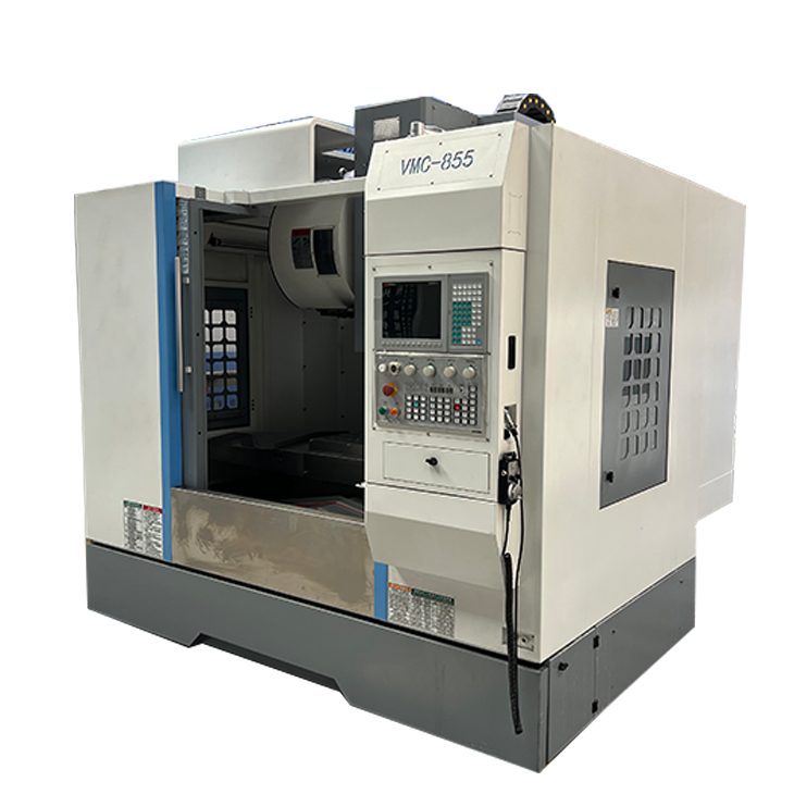
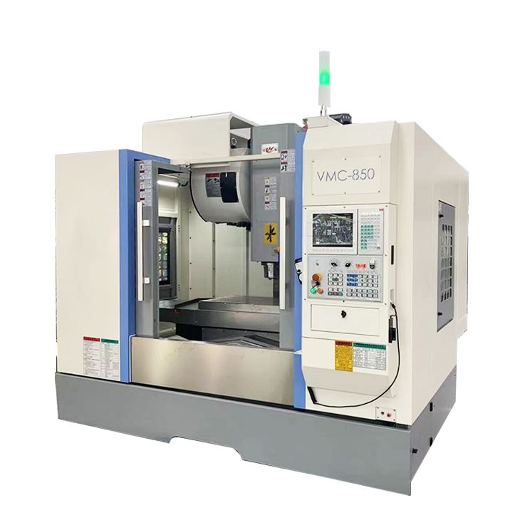
System composition of CNC horizontal machining center
2024-06-18
-
A method to solve the problem of spindle shaking in CNC lathes
2024-06-15
-
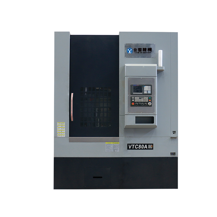
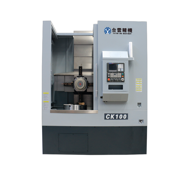
In which industry is the most widely used CNC vertical lathe?
2024-06-04
-
How to clamp the workpiece on a CNC vertical lathe?
2024-05-29
-
CNC milling machine machining center commonly used accessories
2024-05-25
-
Steps for adjusting the turret of a CNC vertical lathe
2024-05-22
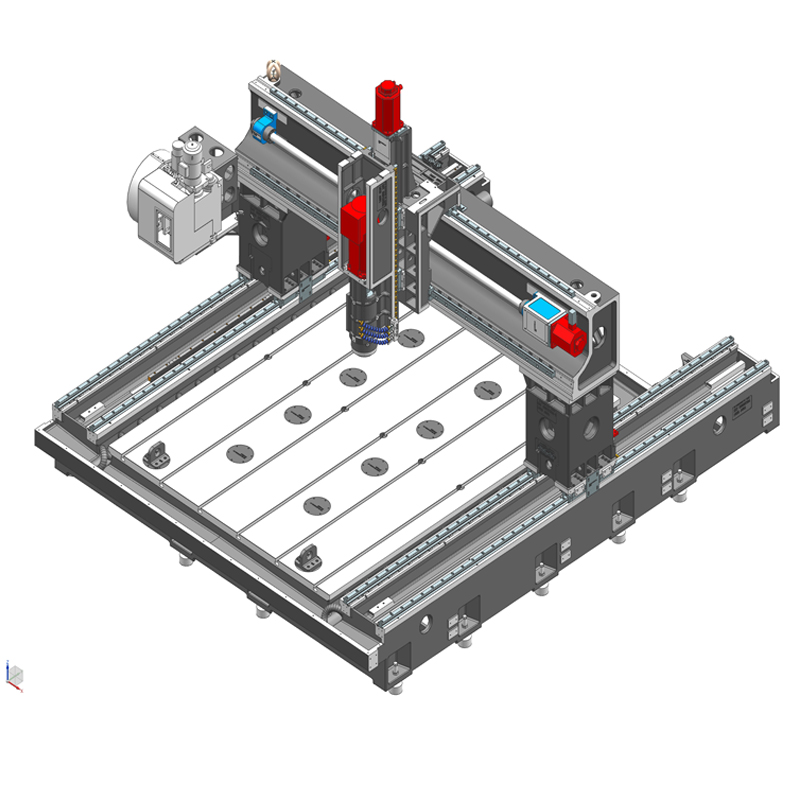
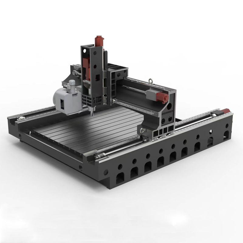
High precision gantry machining center
The high-precision gantry machining center is a professional CNC machining equipment with the following characteristics:...
The high-precision gantry machining center is a professional CNC machining equipment with the following characteristics:
1. High-precision machining: The high-precision gantry machining center is equipped with high-precision guide rails, servo drive systems and precision spindles. The high-precision gantry machining center can achieve high-precision processing of workpieces and meet application fields that require high processing accuracy. Such as aerospace, mold manufacturing, etc.
2. Good stability: The gantry structure of the high-precision gantry machining center has strong stability and can withstand large workpiece weights and cutting forces, maintaining the stability of the processing process and helping to improve processing accuracy and surface quality.
3. Wide processing range: The high-precision gantry machining center has a large processing range and workbench size, and can process large workpieces or multiple workpieces at the same time, improving production efficiency.
4. Multi-function processing: Gantry machining centers are usually equipped with multi-axis CNC systems, which can realize a variety of processing functions, including milling, drilling, boring, tapping, etc., to meet the processing needs of complex workpieces.
5. Automated processing: High-precision gantry machining centers are usually equipped with automated equipment such as automatic tool changing systems and automatic workpiece measurement systems, which can realize automated processing. High-precision gantry machining centers improve production efficiency and processing accuracy.
6. Strong flexibility: The gantry machining center has strong processing flexibility, can adjust and optimize the program according to processing needs, and is suitable for processing workpieces of different shapes and materials.
In general, the high-precision gantry machining center is a high-performance, high-precision CNC machining equipment that is suitable for application fields that require high machining accuracy. It can realize a variety of machining functions and improve production efficiency and product quality.
| Processing specifications/machine models | unit | SMA/T1612 | SMA/T1620 | SMA/T1625 | SMA/T2025 | SMA/T2030 | SMA/T2080 | SMA/T2530 | SMA/T2540 | SMA/T3050 | SMA/T3060 |
| Work content | |||||||||||
| working desk size | MM | 1600*1200 | 1600*2000 | 1600*2500 | 2000*2500 | 2000*3000 | 2000*8000 | 2500*3000 | 2500*4000 | 3000*5000 | 3000*6000 |
| X*Y axis travel | MM | 1600*1200 | 1600*2000 | 1600*2500 | 2000*2500 | 2000*3000 | 2000*8000 | 2500*3000 | 2500*4000 | 3000*5000 | 3000*6000 |
| Z-axis travel (up and down) | MM | 350 | 350 | 350 | 550 | 550 | 550 | 550 | 550 | 550 | 550 |
| Distance between worktable and nose of spindle | MM | 100-450 | 100-450 | 100-450 | 170-720 | 170-720 | 170-720 | 170-720 | 170-720 | 170-720 | 170-720 |
| Gantry width | MM | 1300 | 1300 | 1300 | 2200 | 2200 | 2200 | 2700 | 2700 | 3200 | 3200 |
| Maximum load of workbench | T | 1 | 1.3 | 1.6 | 4 | 5 | 10 | 5 | 6 | 8 | 8 |
| Spindle specifications | BT | BT40 direct connection | BT40 direct connection | BT40 direct connection | BT40 direct connection | BT40 direct connection | BT40 direct connection | BT40 direct connection | BT40 direct connection | BT40 direct connection | BT40 direct connection |
| Spindle transmission structure | / | Mechanical spindle | Mechanical spindle | Mechanical spindle | Mechanical spindle | Mechanical spindle | Mechanical spindle | Mechanical spindle | Mechanical spindle | Mechanical spindle | Mechanical spindle |
| Spindle speed | RPM | 12000 | 12000 | 12000 | 12000 | 12000 | 12000 | 12000 | 12000 | 12000 | 12000 |
| Select the model and speed of the electric spindle | HSK | A63 | A63 | A63 | A63 | A63 | A63 | A63 | A63 | A63 | A63 |
| Spindle speed | RPM | 18000 | 18000 | 18000 | 18000 | 18000 | 18000 | 18000 | 18000 | 18000 | 18000 |
| Tool magazine structure A (specify when ordering) | PCS | disc type | disc type | disc type | Robotic arm disc | Robotic arm disc | Robotic arm disc | Robotic arm disc | Robotic arm disc | Robotic arm disc | Robotic arm disc |
| Tool magazine capacity | BT40-24T | BT40-24T | BT40-24T | BT40-24T | BT40-24T | BT40-24T | BT40-24T | BT40-24T | BT40-24T | BT40-24T | |
| Tool changing time T-T | MM | 2.2 | 2.2 | 2.2 | 2.2 | 2.2 | 2.2 | 2.2 | 2.2 | 2.2 | 2.2 |
| Tool magazine structure T (specify when ordering) | Clamp type | Clamp type | Clamp type | Clamp type | Clamp type | Clamp type | Clamp type | Clamp type | Clamp type | Clamp type | |
| Tool magazine capacity | BT40-16T | BT40-16T | BT40-16T | BT40-16T | BT40-16T | BT40-16T | BT40-16T | BT40-16T | BT40-16T | BT40-16T | |
| Tool changing time T-T | MM | 1.8 | 1.8 | 1.8 | 1.8 | 1.8 | 1.8 | 1.8 | 1.8 | 1.8 | 1.8 |
| Maximum tool weight | KG | 8 | 8 | 8 | 8 | 8 | 8 | 8 | 8 | 8 | 8 |
| Feed content | |||||||||||
| G00 rapid traverse (X/Y axis) | M/MIN | 32.48 | 32.48 | 32.48 | 32.48 | 32.48 | 32.48 | 32.48 | 32.48 | 32.48 | 32.48 |
| G00 Y-axis rack rapid feed | MM/MIN | / | / | / | 48 | 48 | 48 | 48 | 48 | 48 | 48 |
| G00 Y-axis screw rapid feed | MM/MIN | 36 | 36 | 36 | 20 | 20 | 20 | 20 | 20 | 20 | 20 |
| G01 cutting feed | MM/MIN | 1-30000 | 1-30000 | 1-30000 | 1-30000 | 1-30000 | 1-30000 | 1-30000 | 1-30000 | 1-30000 | 1-30000 |
| Servo motor specifications | NM | 22.22.22B | 22.22.22B | 22.22.22B | 22.22.22B | 22.22.22B | 22.22.22B | 22.22.22B | 30.30.22B | 30.30.22B | 30.30.22B |
| Servo motor speed | RPM | 2000/3000 | 2000/3000 | 2000/3000 | 2000/3000 | 2000/3000 | 2000/3000 | 2000/3000 | 2000/3000 | 2000/3000 | 2000/3000 |
| X.Y.Z motor connection method | / | Direct | Direct | Direct | Direct | Direct | Direct | Direct | Direct | Direct | Direct |
| X.Z axis ball screw specifications | MM | 50-40 | 50-40 | 50-40 | 50-40 | 50-40 | 50-40 | 50-40 | 50-40 | 63-40 | 63-40 |
| Y-axis structure | / | Single drive | Single drive | Single drive | Single drive/dual drive | Single drive/dual drive | Dual drive | Dual drive | Dual drive | Dual drive | Dual drive |
| Y-axis rack (standard) specifications | M | / | M3/1:10 | M3/1:10 | M3/1:10 | M3/1:10 | M3/1:10 | M3/1:10 | M3/1:10 | ||
| Y-axis screw (standard) specifications | MM | 5020 | 5020 | 5020 | 5020 | 5020 | 5020 | 6320 | / | / | / |
| X-axis rail specifications | MM | 45 ball | 45 ball | 45 ball | 45 ball | 45 ball | 45 ball | 45 ball | 45 ball | 45 ball | 45 ball |
| Y axis rail specifications | MM | 45 ball | 45 ball | 45 ball | 45 ball | 45 ball*2 | 45 ball*2 | 45 ball*2 | 45 ball*2 | 45 ball*2 | 45 ball*2 |
| Z axis rail specifications | MM | 35 ball | 35 ball | 35 ball | 35 ball | 35 ball | 35 ball | 35 ball | 35 ball | 35 ball | 35 ball |
| Precise positioning of X.Z axis items | MM | ±0.01 | ±0.01 | ±0.01 | ±0.01 | ±0.01 | ±0.01 | ±0.01 | ±0.01 | ±0.01 | ±0.01 |
| X.Z axis repeat position precision | MM | ±0.005 | ±0.005 | ±0.005 | ±0.005 | ±0.005 | ±0.005 | ±0.005 | ±0.005 | ±0.005 | ±0.005 |
| Y-axis positioning accuracy | MM | ±0.02 | ±0.02 | ±0.02 | ±0.02 | ±0.02 | ±0.02 | ±0.02 | ±0.02 | ±0.02 | ±0.02 |
| Minimum move value | MM | 0.001 | 0.001 | 0.001 | 0.001 | 0.001 | 0.001 | 0.001 | 0.001 | 0.001 | 0.001 |
| Oil and gas pressure system | |||||||||||
| air pressure | KG/MM | 6.5 | 6.5 | 6.5 | 6.5 | 6.5 | 6.5 | 6.5 | 6.5 | 6.5 | 6.5 |
| Bed block height | MM | 40 | 40 | 40 | 40 | 40 | 40 | 40 | 40 | 40 | 40 |
| Lubricating oil capacity | L | 4 | 4 | 4 | 4 | 4 | 4 | 4 | 4 | 4 | 4 |
| battery capacity | KW | 25 | 25 | 25 | 25 | 25 | 25 | 30 | 30 | 30 | 30 |
| coolant capacity | L | 180 | 180 | 180 | 220 | 220 | 220 | 320 | 320 | 320 | 320 |
| Form factor | |||||||||||
| Machine weight | T | 8 | 10 | 12 | 14 | 16 | 48 | 18 | 23 | 32 | 36 |
| Machine length | MM | 2200 | 3000 | 3300 | 4000 | 4500 | 10000 | 4300 | 5000 | 6000 | 7000 |
| Machine width | 2300 | 2300 | 2300 | 3200 | 3200 | 3200 | 2800 | 2800 | 3600 | 3600 | |
| Machine height (maximum) | MM | 1800 | 1800 | 1800 | 2100 | 2100 | 2100 | 2100 | 2100 | 2100 | 2100 |
| Machine height (minimum) | MM | 1300 | 1300 | 1300 | 1800 | 1800 | 1800 | 1800 | 1800 | 1800 | 1800 |
| Chip removal method (optional) | / | Twin screw | Twin screw | Twin screw | Twin screw | Twin screw | Twin screw | Twin screw | Twin screw | Twin screw | Twin screw |

 English
 日本語
日本語 한국어
한국어 Россия
  Français
 España
 عرب .
عرب .  Português
 Deutsch
 भारत
भारत Нидерланды
