English
 日本語
日本語 한국어
한국어 Россия
  Français
 España
 عرب .
عرب .  Português
 Deutsch
 भारत
भारत Нидерланды

- Recommended news
-
System composition of CNC horizontal machining center
2024-06-18
-
A method to solve the problem of spindle shaking in CNC lathes
2024-06-15
-
In which industry is the most widely used CNC vertical lathe?
2024-06-04
-
How to clamp the workpiece on a CNC vertical lathe?
2024-05-29
-
CNC milling machine machining center commonly used accessories
2024-05-25
-
Steps for adjusting the turret of a CNC vertical lathe
2024-05-22
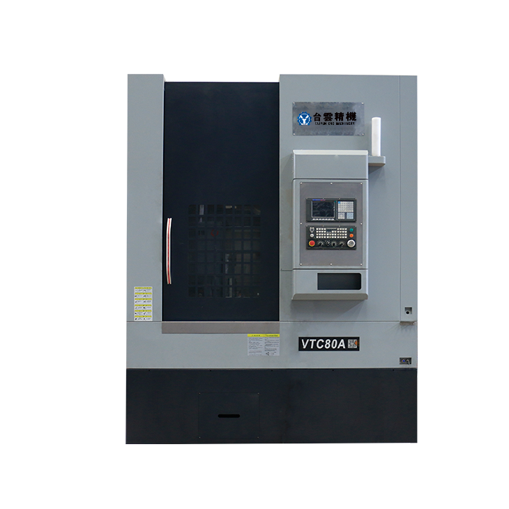
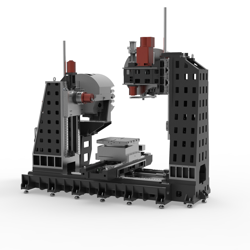
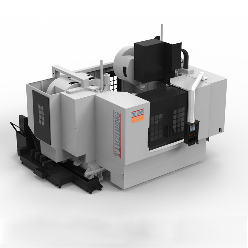
High speed machining center
A high-speed machining center is a CNC machine tool specially used for high-speed and high-efficiency processing....


A high-speed machining center is a CNC machine tool specially used for high-speed and high-efficiency processing. It usually has the following features and functions:
1. High-speed spindle: High-speed machining centers are equipped with high-speed spindles. The spindle speed can usually reach tens of thousands of revolutions per minute, which helps achieve fast cutting and high-precision processing.
2. High-speed feed: The feed system of the high-speed machining center is designed to be high-speed and high-precision, which can achieve fast feed and rapid positioning and improve processing efficiency.
3. High-precision control: The high-speed machining center adopts an advanced CNC system, which can accurately control processing parameters and paths to achieve high-precision processing effects.
4. Multi-axis linkage: High-speed machining centers are usually equipped with multi-axis linkage functions (such as three-axis, four-axis, five-axis, etc.), which can process complex shapes and structures and increase processing flexibility.
5. Quick tool change system: High-speed machining centers are usually equipped with automatic tool change systems, which can quickly change tools, improve processing efficiency, and reduce downtime.
6. Automation and intelligence: High-speed machining centers usually have automation and intelligence functions, such as automatic measurement, automatic compensation, fault diagnosis, etc., to reduce manual intervention and improve processing efficiency and quality.
7. Cooling and lubrication system: The high-speed machining center is equipped with an efficient cooling and lubrication system to maintain stable temperatures in the processing area and tools, extend tool life, and improve processing quality.
8. Strong adaptability: High-speed machining centers can adapt to the processing of a variety of materials, including metals, plastics, composite materials, etc., and are widely used in aerospace, automobiles, electronics, medical equipment and other industries.
9. Rigidity and stability: The structural design of the high-speed machining center focuses on rigidity and stability, which can maintain stability during high-speed processing and reduce vibration and errors.
The high-speed machining center is an efficient and precise CNC machine tool suitable for high-speed machining tasks. It can meet the processing needs of complex workpieces and improve production efficiency and processing quality.
| Specifications/model | unit | VW50A | VW63A | VW80A | VW50C | VW63B | VW80B | VW50C | VW63C | VW80C | VW63D | VW80D | VW100D |
| Spindle position result | Same side of the cross | Same side of the cross | Same side of the cross | Same side of the cross | Same side of the cross | Same side of the cross | Contralateral simultaneous processing | Contralateral simultaneous processing | Contralateral simultaneous processing | Inverted T-shaped same side | Inverted T-shaped same side | Inverted T-shaped same side | |
| Work content | |||||||||||||
| Horizontal X (left and right), Y (up and down), Z (front and back) | CM | 80、55、550 | 110、60、60 | 130、80、70 | 80、60、50 | 110、80、70 | 130、90、80 | 80、60、50 | 110、80、70 | 130、90、80 | 105、80、60 | 160、80、70 | 200、90、80 |
| Vertical X (left and right), Y (front and back), Z (up and down) | CM | 80、55、550 | 110、60、55 | 130、70、70 | 80、60、60 | 110、70、70 | 130、80、90 | 80、60、60 | 110、70、70 | 130、80、80 | 105、70、70 | 160、80、80 | 200、80、90 |
| Workbench area (can be customized) | MM | 500×500 | 630×630 | 800×800 | 500×500 | 630×630 | 800×800 | 500×500 | 630×630 | 800×800 | 630×630 | 800×800 | 1000×1000 |
| Maximum load | KG | 600 | 800 | 1500 | 600 | 1100 | 1800 | 600 | 1100 | 1800 | 1200 | 1800 | 2200 |
| T-shaped slot (slot width × number of slots) | MM | 18×3 | 20×3 | 22×5 | 18×3 | 22×3 | 22×5 | 18×3 | 22×3 | 22×5 | 22×5 | 28×5 | 28×7 |
| Standard dividing angle of workbench | ℃ | any equal portion | any equal portion | any equal portion | any equal portion | any equal portion | any equal portion | any equal portion | any equal portion | any equal portion | any equal portion | any equal portion | any equal portion |
| Workbench split angle (customized) | ℃ | 1、5、90 | 1、5、90 | 1、5、90 | 1、5、90 | 1、5、90 | 1、5、90 | 1、5、90 | 1、5、90 | 1、5、90 | 1、5、90 | 1、5、90 | 1、5、90 |
| Processing range | |||||||||||||
| Distance from horizontal spindle center to worktable | -200+500 | -200+600 | -200+800 | +50-650 | +50-850 | +50-950 | +50-650 | +50-850 | +50-950 | -200+600 | -200+700 | -200+800 | |
| Horizontal spindle nose to the side of the workbench | MM | +100-450 | +100-500 | +100-600 | +100-500 | +150-550 | +200-600 | +100-50 | +150-550 | +200-600 | +100-500 | +100-600 | +100-700 |
| Distance from vertical spindle nose to work surface | MM | +200+750 | +200+800 | +200+900 | +150-750 | +150-850 | +150-1050 | +150-750 | +150-850 | +150-1050 | +200+800 | +200+1000 | +200+1100 |
| Maximum height/diameter of workpiece | MM | 500/900 | 600/1300 | 800/1500 | 500/900 | 600/1300 | 800/1500 | 500/900 | 600/1300 | 800/1500 | 700/900 | 800/1300 | 900/1500 |
| Spindle content | |||||||||||||
| handle form | / | BT40 | BT40 | BT50 | BT40 | BT50 | BT50 | BT40 | BT50 | BT50 | BT50 | BT50 | BT50 |
| Maximum speed of vertical and horizontal spindles | RPM | 8000 | 8000 | 6000 | 8000 | 6000 | 6000 | 8000 | 6000 | 6000 | 6000 | 6000 | 6000 |
| Maximum speed of vertical and horizontal spindle (optional) | RPM | 12000 | 12000 | 6000 | 12000 | 6000 | 6000 | 12000 | 6000 | 6000 | 6000 | 6000 | 6000 |
| Tool magazine content | / | ||||||||||||
| horizontal structure | / | Robotic arm | Robotic arm | Robotic arm | Robotic arm | Robotic arm | Robotic arm | Robotic arm | Robotic arm | Robotic arm | Robotic arm | Robotic arm | Robotic arm |
| Maximum tool diameter | MM | 350 | 350 | 350 | 350 | 350 | 350 | 350 | 350 | 350 | 350 | 350 | 350 |
| Maximum tool weight | KG | 8 | 8 | 15 | 8 | 15 | 15 | 8 | 15 | 15 | 15 | 15 | 15 |
| Number of horizontal and vertical tools | T | 24/24 | 24/24 | 24/24 | 24/24 | 24/24 | 24/24 | 24/24 | 24/24 | 24/24 | 24/24 | 24/24 | 24/24 |
| Three-axis rapid traverse speed | M/MIN | 32/32/32 | 32/32/32 | 24/24/24 | 32/32/32 | 32/32/32 | 24/24/24 | 32/32/32 | 32/32/32 | 24/24/24 | 32/32/32 | 24/24/24 | 24/24/24 |
| Axis servo motor | |||||||||||||
| Spindle motor horizontal/vertical | KW | 11/11 | 11/11 | 18.5/18.5 | 11/11 | 18.5/18.5 | 18.5/18.5 | 11/11 | 18.5/18.5 | 18.5/18.5 | 18.5/18.5 | 18.5/18.5 | 18.5/18.5 |
| X, Y, Z axis, B | NM | 22/22/22/12 | 22/22/22/22 | 27/27/27/22 | 22/22/22/22 | 27/27/27/22 | 27/27/27/22 | 22/22/22/22 | 27/27/27/22 | 27/27/27/22 | 27/27/27/22 | 27/27/27/22 | 27/27/27/30 |
| X-axis guide rail, screw rod | MM | Roller 45+screw 40 | Roller 45+screw 40 | Roller 55+screw 50 | Roller 45+screw 40 | Roller 45+screw 40 | Roller 55+screw 50 | Roller 45+screw 40 | Roller 45+screw 40 | Roller 55+screw 50 | Roller 45+screw 40 | Roller 55+screw 50 | Roller 55+screw 50 |
| Y-axis guide rail, screw rod | MM | Roller 45+screw 40 | Roller 45+screw 40 | Roller 55+screw 50 | Roller 45+screw 40 | Roller 45+screw 40 | Roller 55+screw 50 | Roller 45+screw 40 | Roller 45+screw 40 | Roller 55+screw 50 | Roller 45+screw 40 | Roller 55+screw 50 | Roller 55+screw 50 |
| Z-axis guide rail, screw rod | MM | Roller 45+screw 40 | Roller 45+screw 40 | Roller 45+screw 40 | Roller 45+screw 40 | Roller 55+screw 50 | Roller 55+screw 50 | Roller 45+screw 40 | Roller 55+screw 50 | Roller 55+screw 50 | Roller 55+screw 50 | Roller 55+screw 50 | Roller 55+screw 50 |
| air pressure | KG | 6.5 | 6.5 | 6.5 | 6.5 | 6.5 | 6.5 | 6.5 | 6.5 | 6.5 | 6.5 | 6.5 | 6.5 |
| Lubricating oil capacity | L | 4 | 4 | 4 | 4 | 4 | 4 | 4 | 4 | 4 | 4 | 4 | 4 |
| battery capacity | KW | 40 | 40 | 60 | 40 | 60 | 60 | 40 | 60 | 60 | 60 | 60 | 60 |
| Cutting system capacity | L | 450 | 550 | 650 | 450 | 550 | 650 | 450 | 550 | 650 | 450 | 550 | 650 |
| Machine weight | T | 8.0 | 9.5 | 15.5 | 10.5 | 15 | 19.5 | 22 | 27.5 | 33.5 | 22 | 27.5 | 33.5 |
| Machine length (front and rear) | MM | 3600 | 3600 | 4600 | 3600 | 4600 | 4600 | 3900 | 5200 | 5500 | 5200 | 5500 | 6500 |
| Machine width (left and right) | MM | 2800 | 3200 | 4200 | 3200 | 5000 | 5000 | 3600 | 5000 | 5000 | 5000 | 5500 | 6000 |
| Machine height (maximum) | MM | 3300 | 3300 | 2700 | 3300 | 3700 | 3700 | 3300 | 3700 | 3700 | 4100 | 4300 | 4700 |
| Chip removal method (optional) | / | single chain plate | single chain plate | single chain plate | single chain plate | single chain plate | single chain plate | single chain plate | single chain plate | single chain plate | single chain plate | single chain plate | single chain plate |
| Chip removal method (optional) | / | Twin screw | Twin screw | Twin screw | Twin screw | Twin screw | Twin screw | Twin screw | Twin screw | Twin screw | Twin screw | Twin screw | Twin screw |
| controller system | CNC | multi-channel | multi-channel | multi-channel | multi-channel | multi-channel | multi-channel | multi-channel | multi-channel | multi-channel | multi-channel | multi-channel | multi-channel |