- Recommended news
-
System composition of CNC horizontal machining center
2024-06-18
-
A method to solve the problem of spindle shaking in CNC lathes
2024-06-15
-
In which industry is the most widely used CNC vertical lathe?
2024-06-04
-
How to clamp the workpiece on a CNC vertical lathe?
2024-05-29
-
CNC milling machine machining center commonly used accessories
2024-05-25
-
Steps for adjusting the turret of a CNC vertical lathe
2024-05-22
Compound horizontal machining center
The compound horizontal machining center is an advanced CNC machine tool that combines turning and milling functions and has the characteristics of an opposing worktable....
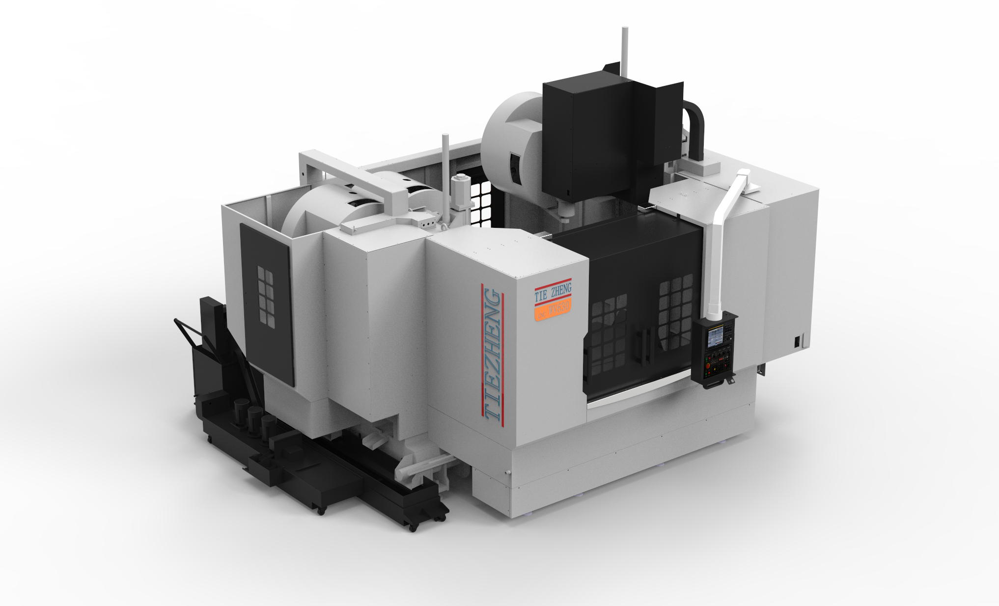
The compound horizontal machining center is an advanced CNC machine tool that combines turning and milling functions and has the characteristics of an opposing worktable. The following are the main features and components of a composite horizontal machining center:
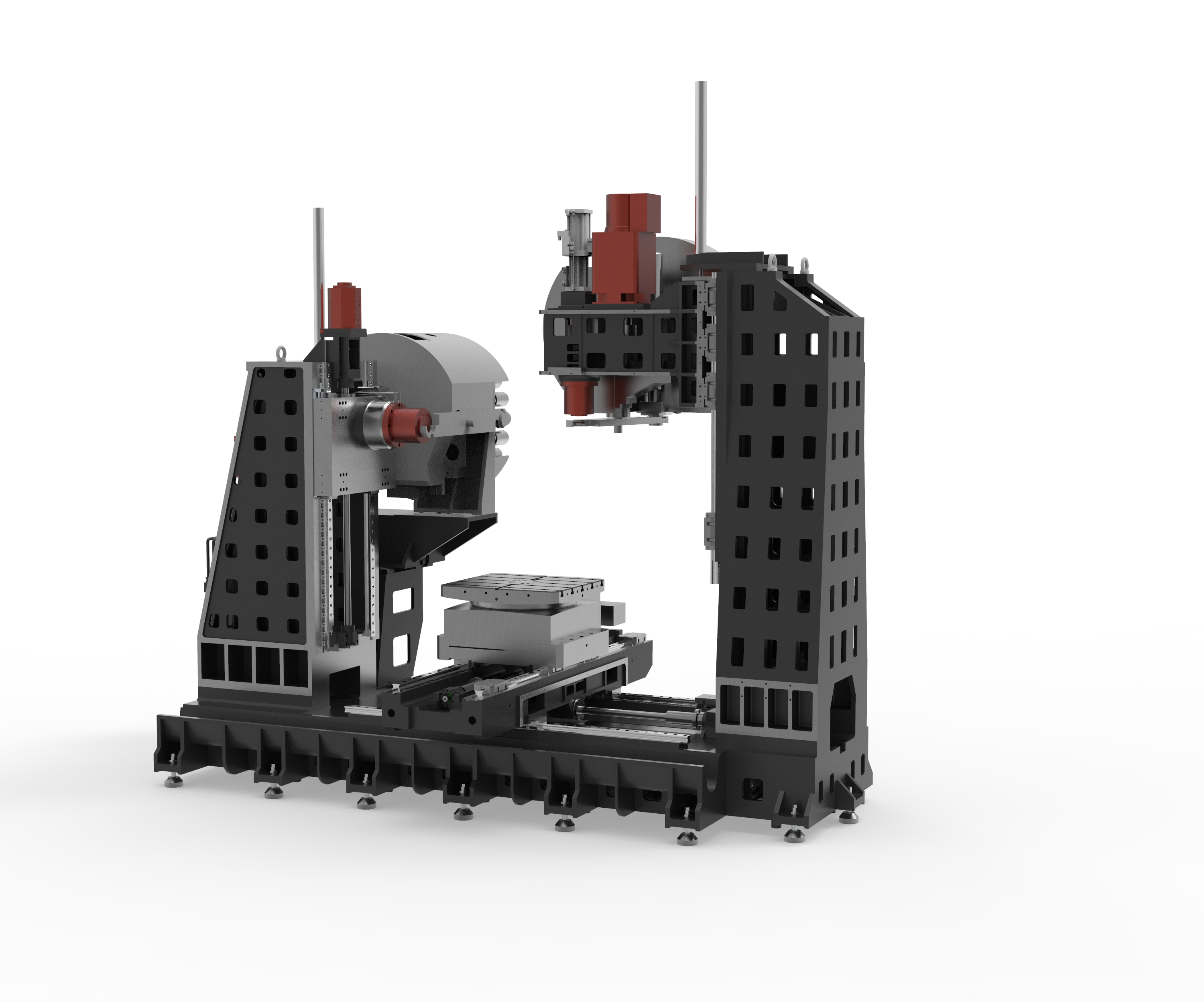
1. Lathe bed structure: Composite horizontal machining centers usually have a solid bed structure, which provides stable basic support.
2. Opposite horizontal worktable: The compound opposite horizontal machining center has two symmetrically arranged worktables, which can perform turning and milling processes respectively. The compound opposite horizontal machining center can also perform compound processing operations at the same time.
3. Turning spindle and milling spindle: The compound horizontal machining center is equipped with a dedicated turning spindle and milling spindle, which are used for turning and milling processing operations respectively.
4. Turret: Compound horizontal machining centers are usually equipped with a turret, which can install different types and specifications of tools to meet different processing needs.
5. CNC system: The compound horizontal machining center adopts an advanced CNC system, which can realize complex processing program control and automated operations.
6. Feeding system: The feeding system of the composite horizontal machining center can achieve high-speed, high-precision feeding movement to ensure processing quality and efficiency.
7. Cooling system: The compound horizontal machining center is equipped with a cooling system, which can cool the cutting area in time and clean the chips, improving processing efficiency and tool life.
8. Automatic tool changer: In order to improve production efficiency, compound horizontal machining centers are usually equipped with an automatic tool changer, which can quickly and accurately change tools.
9. Safety protection devices: The composite horizontal machining center is equipped with various safety protection devices, including protective covers, emergency stop buttons, etc., to ensure the safety of operators.
The composite horizontal machining center is efficient, flexible and multi-functional. It is widely used in automobile, aerospace, mold manufacturing and other industries. It is one of the important equipment in modern manufacturing industry.
| Specifications/model | Unit | WHH50 | WHH63 | WHH80 | WHH100 |
| Work content | |||||
| Turntable table size WHA | MM | 500×500 | 630×630 | 800×800 | 1000×1000 |
| Fixed table size WHF (optional) | MM | 1000×500 | 1300×600 | 1300×600 | 1600×1000 |
| Number of worktables (optional translational double work) | N | Single/Double | Single/Double | Single/Double | Single/Double |
| Workbench indexing (standard) | N | 1 degree 1 minute | 1 degree 1 minute | 1 degree 1 minute | 1 degree 1 minute |
| Workbench (optional) | N | Other graduations can be customized | Other graduations can be customized | Other graduations can be customized | Other graduations can be customized |
| Maximum rotation diameter of worktable | MM | 1000 | 1300 | 1300 | 1600 |
| X1.X2 axis travel | MM | 800 | 1000 | 1000 | 1300 |
| Y1.Y2 axis travel (spindle item moves up and down) | MM | 700 | 700 | 700 | 700 |
| Z1.Z2 axis stroke | MM | 500 | 900 | 900 | 900 |
| Distance from spindle center to worktable | MM | 110-810 | 110-810 | 110-810 | 110-810 |
| Distance from spindle end face to worktable center | MM | 200-700 | 200-1100 | 200-1100 | 200-1100 |
| T-shaped workbench (slot width * number of slots) | MM | 22-3 | 22-3 | 22-5 | 22-5 |
| Workbench load-bearing | KG | 2000 | 2500 | 3200 | 5000 |
| Spindle and spindle box specifications | |||||
| Spindle taper hole (model/installation dimensions) | ISO | BT40-150 | BT50-190 | BT50-190 | BT50-190 |
| Spindle speed mark (optional) | RPM | 4000/8000/12000 | 4000/6000 | 4000/6000 | 4000/6000 |
| Feeding system | |||||
| X.Y.Z axis screw specifications | MM | 40/40/40 | 50/50/50 | 50/50/50 | 63/50/50 |
| X-axis rapid movement speed | M/MIN | X:48 | X:32 | X:32 | X:24 |
| Y-axis rapid movement speed | M/MIN | Y:48 | Y:32 | Y:32 | Y:24 |
| Z-axis rapid movement speed | M/MIN | Z:48 | Z:32 | Z:32 | Z:24 |
| X/Y/Z axis wire gauge specifications | MM | Roller 45/45/45 | Roller 55/55/55 | Roller 55/55/55 | Roller 55/55/55 |
| X/Y/Z motor connection method | / | direct connection | direct connection | direct connection | direct connection |
| main motor power | KW | 11 | 18.5 | 18.5 | 18.5 |
| X-axis motor power | NM | 22/22B/22 | 27/27B/27 | 27/27B/27 | 30/30B/30 |
| B-axis motor power | NM | B:8 | 12 | 12 | 22 |
| Axis positioning accuracy | MM | ±0.005/300 | ±0.005/300 | ±0.005/300 | ±0.005/300 |
| Axis item repeat positioning accuracy | MM | ±0.003/300 | ±0.003/300 | ±0.003/300 | ±0.003/300 |
| BPositioning accuracy | MM | 8” | 8” | 8” | 8” |
| B Repeat positioning accuracy | MM | 5” | 5” | 5” | 5” |
| Minimum move value | MM | 0.001 | 0.001 | 0.001 | 0.001 |
| Oil and gas pressure system | |||||
| air pressure | KG | 7 | 7 | 7 | 7 |
| coolant capacity | L | 550 | 650 | 650 | 850 |
| Lubricating oil capacity L | L | 4 | 4 | 4 | 4 |
| Toolholder/Tool Magazine System (specify when ordering) | |||||
| Tool magazine structure | / | Robotic arm | Robotic arm | Robotic arm | Robotic arm |
| Number of tool magazines | T | 24 | 24 | 24 | 24 |
| Tool changing time T-T | MM | 3 | 7 | 7 | 7 |
| Maximum tool weight | KGS | 8 | 12 | 12 | 12 |
| Form factor | |||||
| Weight approx. | KG | 10/11 | 19/20 | 21/22 | 28/30 |
| Machine length | MM | 5500 | 7500 | 7500 | 9500 |
| Machine width | MM | 3800 | 4500 | 4500 | 5500 |
| Machine height (maximum) | MM | 3300 | 3700 | 3700 | 4200 |
| Machine height (minimum) | MM | 3000 | 3300 | 3300 | 3600 |
| Chip removal method | / | win screw + single chain plate | win screw + double chain plate | win screw + double chain plate | win screw + double chain plate |

 English
 日本語
日本語 한국어
한국어 Россия
  Français
 España
 عرب .
عرب .  Português
 Deutsch
 भारत
भारत Нидерланды
