- Recommended news
-
System composition of CNC horizontal machining center
2024-06-18
-
A method to solve the problem of spindle shaking in CNC lathes
2024-06-15
-
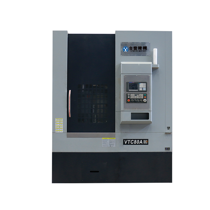
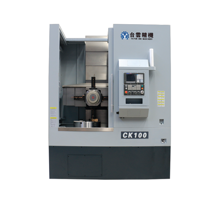
In which industry is the most widely used CNC vertical lathe?
2024-06-04
-
How to clamp the workpiece on a CNC vertical lathe?
2024-05-29
-
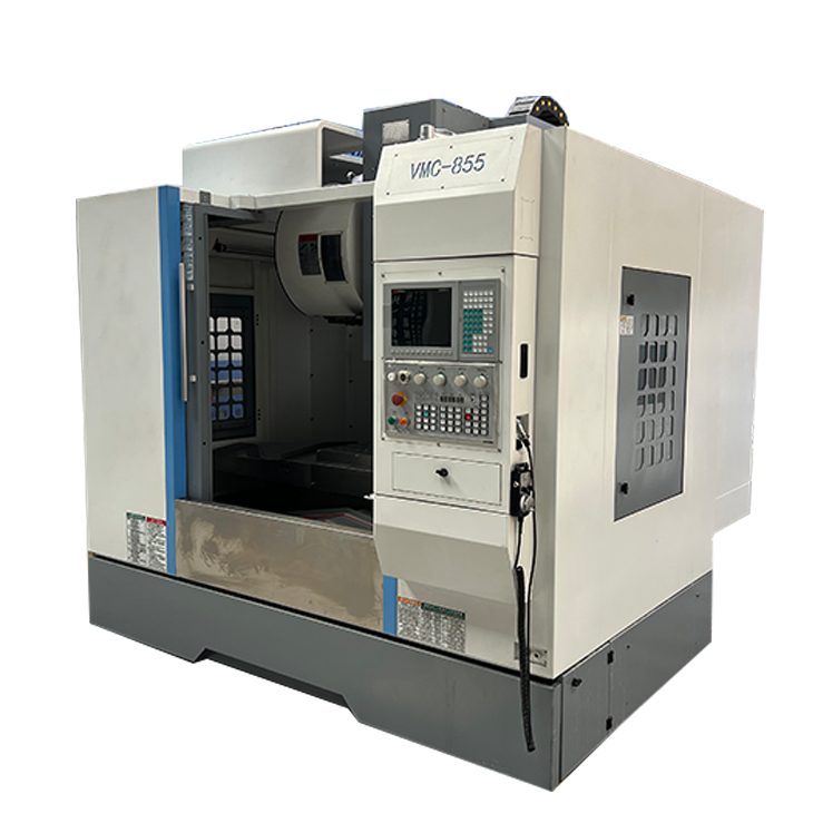
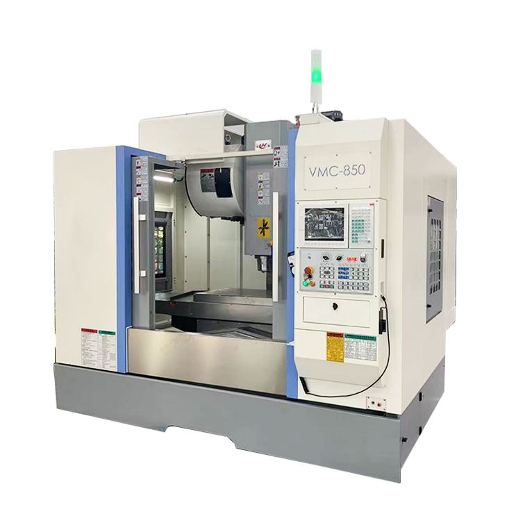
CNC milling machine machining center commonly used accessories
2024-05-25
-
Steps for adjusting the turret of a CNC vertical lathe
2024-05-22
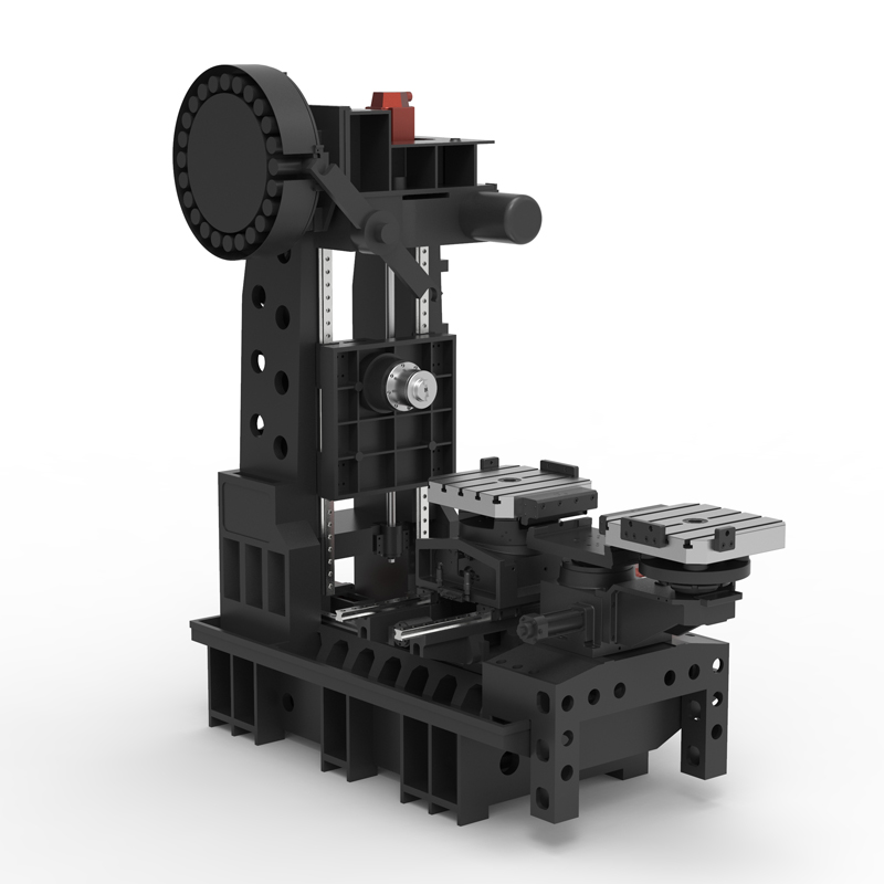
Horizontal cross structure machining center
The horizontal cross structure machining center is one of the indispensable and important equipment in modern manufacturing industry....
The horizontal cross structure machining center is one of the indispensable and important equipment in modern manufacturing industry. The horizontal cross structure machining center has become the best choice for many companies to improve production efficiency due to its high precision, high efficiency and strong flexibility.
1. Working principle
The horizontal cross structure machining center adopts a cross beam structure, that is, the cross beam and the vertical and horizontal bed are in a cross shape. This structure makes the machining center highly stable and rigid, can withstand large load cutting forces, and ensures machining accuracy and quality. At the same time, the horizontal structure also facilitates the clamping and unloading of workpieces, improving production efficiency.
2. Advantages
High-precision processing capability: The horizontal cross structure machining center adopts high-precision guide rails and ball screws, which enables the positioning accuracy and repetitive positioning accuracy during the processing to reach a very high level. This is a very important advantage for parts that require precision machining.
High-speed cutting capability: The horizontal cross-structure machining center is equipped with a high-speed spindle and a high-rigidity cutting system, which can withstand vibration and load during high-speed cutting, ensuring the cutting effect and processing speed. This can significantly improve production efficiency for companies that require large amounts of processing.
Multi-functional processing capabilities: The horizontal cross structure machining center has multi-axis processing functions and can perform vertical milling, horizontal milling, vertical milling, hole processing and other operations. The multi-functional design of the horizontal cross structure machining center allows the machining center to adapt to processing parts of different shapes and requirements, providing more flexible and diverse processing solutions.
3. Application fields
Horizontal cross structure machining centers are widely used in aerospace, automobile manufacturing, mold manufacturing, machining and other industries. Specific applications include: processing of precision parts, manufacturing of molds, processing of shaft parts, milling, and polishing of complex curved surfaces, etc. Horizontal cross structure machining center can meet various processing needs of different industries and become a powerful tool to improve production efficiency and product quality.
To sum up, the horizontal cross structure machining center has become an important equipment for improving production efficiency in all walks of life due to its high precision, high efficiency and high flexibility. By understanding its working principle, advantages and application areas, you can make better use of this tool and improve your company's competitiveness and production capacity.
| Specifications/model | Unit | WA50 | WA63 | WA80 |
| Work content | ||||
| Installation turntable specifications (optional) | MM | 500*500 | 630*630 | 800*800 |
| Workbench indexing (standard) | N | 1 degree 1 minute | 1 degree 1 minute | 1 degree 1 minute |
| Customized workbench (optional) | N | Customize other graduations | Customize other graduations | Customize other graduations |
| Maximum rotation diameter of worktable | MM | 850 | 1150 | 1300 |
| X-axis travel | MM | 800 | 1100 | 1300 |
| Y-axis travel (headstock moves up and down) | MM | 550 | 750 | 900 |
| Z-axis travel | MM | 500 | 600 | 700 |
| Distance from spindle center to worktable | MM | 110-660 | 110-860 | 110-1010 |
| Distance from spindle end face to worktable center | MM | 250-650 | 210-710 | 300-900 |
| Workbench (slot width*number of slots) | MM | 3-14 | 5-14 | 5-14 |
| Threaded hole (optional) | MM | 24-M14 | 24-M14 | 24-M14 |
| Workbench load-bearing | KG | 600 | 800 | 1000 |
| Spindle and spindle box specifications | ||||
| Spindle taper hole | ISO | BT40-150 | BT50-150 | BT50-190 |
| Spindle speed | RPM | 8000 | 8000 | 8000 |
| Feeding system | ||||
| Shaft Ball Screw Specifications | MM | 40/40/40 | 40/40/40 | 40/40/40 |
| X-axis rapid movement speed | M/MIN | X:48 | X:32 | X:32 |
| Y-axis rapid movement speed | M/MIN | Y:48 | Y:32 | Y:32 |
| Z-axis rapid movement speed | M/MIN | Z:48 | Z:32 | Z:32 |
| X/Y/Z axis rail specifications | MM | Roller 35/45/45 | Roller 45/45/45 | Roller 45/45/45 |
| Motor connection method | / | Direct | Direct | Direct |
| Main motor parameters | KW | 11 | 11 | 15 |
| X-axis motor power | NM | X:22 | X:22 | X:22 |
| Y-axis motor power | NM | Y:22B | Y:22B | Y:22B |
| Z-axis motor power | NM | Z:22 | Z:22 | Z;30 |
| B-axis motor power | NM | B:8 | B:12 | B:12 |
| Axis positioning accuracy | MM | ±0.005 | ±0.005 | ±0.005 |
| Axis item repeat positioning accuracy | MM | ±0.003 | ±0.003 | ±0.003 |
| BPositioning accuracy | MM | 10" | 10" | 10" |
| B Repeat positioning accuracy | MM | 5" | 5" | 5" |
| Minimum move value | MM | 0.001 | 0.001 | 0.001 |
| Oil and gas pressure system | ||||
| air pressure | KG/MM | 6.5 | 6.5 | 6.5 |
| coolant capacity | L | 450 | 450 | 450 |
| Lubricating oil capacity L | L | 4 | 4 | 4 |
| Toolholder/Tool Magazine System (specify when ordering) | ||||
| Tool magazine structure | / | Top disc type | Top disc type | Top disc type |
| Number of tool magazines (optional) | T | twenty four | twenty four | twenty four |
| Tool changing time | MM | 3.2 | 3.2 | 3.2 |
| Maximum tool weight | KGS | 12 | 15 | 15 |
| Form factor | ||||
| Weight approx. | KG | 6.5 | 8.5 | 10 |
| Machine length | MM | 3500 | 3800 | 4000 |
| Machine width | MM | 2500 | 3000 | 3500 |
| Machine width (height) | MM | 2800 | 3000 | 3300 |
| Machine height (minimum) | MM | 2300 | 2500 | 2900 |
| Machine tool structure | / | Cross type | Cross type | Cross type |
| Chip removal method | / | back row | back row | back row |

 English
 日本語
日本語 한국어
한국어 Россия
  Français
 España
 عرب .
عرب .  Português
 Deutsch
 भारत
भारत Нидерланды
