- Recommended news
-
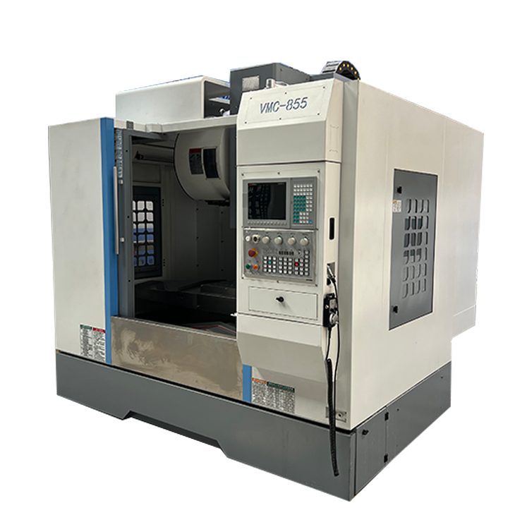
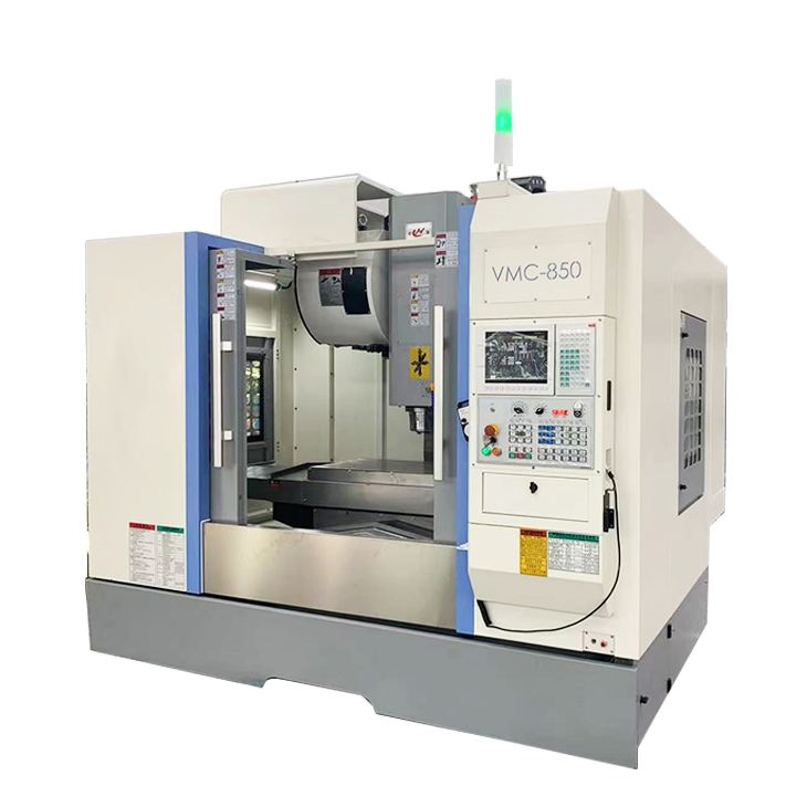
System composition of CNC horizontal machining center
2024-06-18
-
A method to solve the problem of spindle shaking in CNC lathes
2024-06-15
-
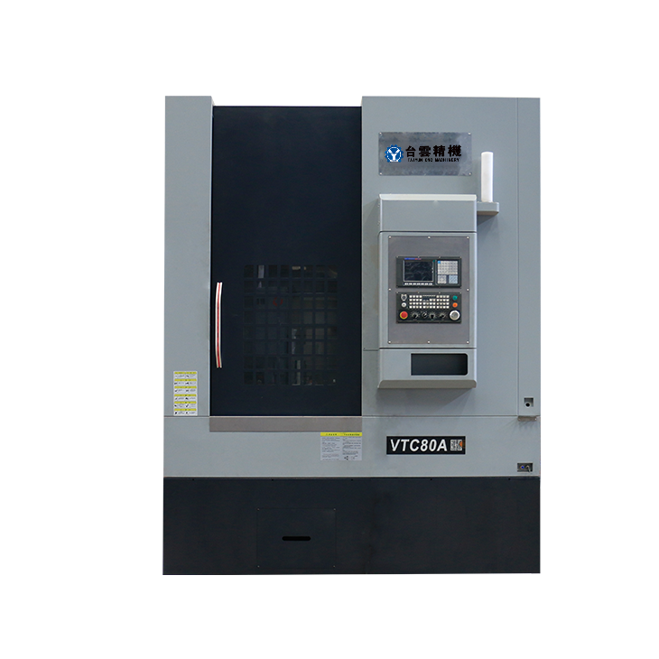
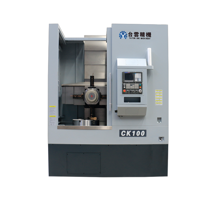
In which industry is the most widely used CNC vertical lathe?
2024-06-04
-
How to clamp the workpiece on a CNC vertical lathe?
2024-05-29
-
CNC milling machine machining center commonly used accessories
2024-05-25
-
Steps for adjusting the turret of a CNC vertical lathe
2024-05-22
Fully automatic horizontal machining center
The fully automatic horizontal machining center is a modern high-precision machine tool equipment with the characteristics of high efficiency, stability and flexibility....
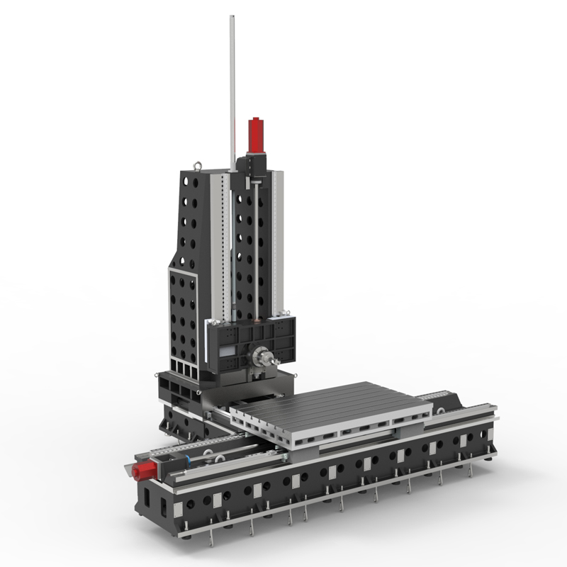
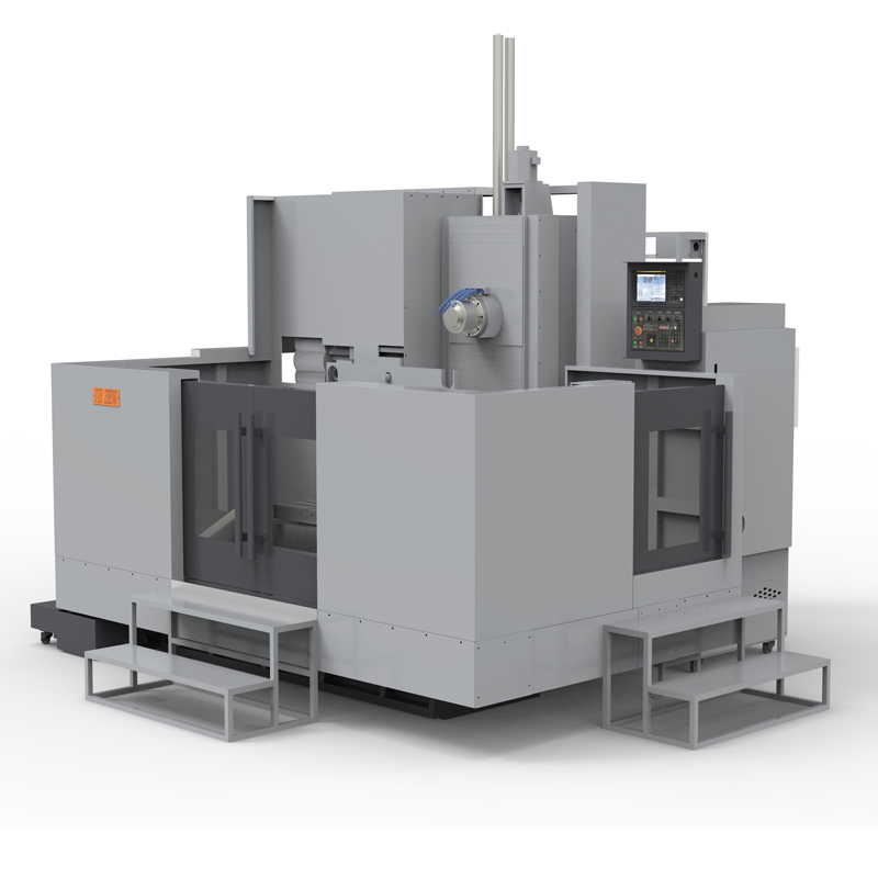
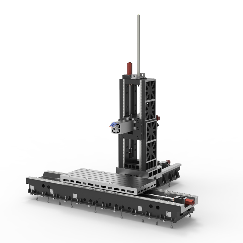
The fully automatic horizontal machining center is a modern high-precision machine tool equipment with the characteristics of high efficiency, stability and flexibility. Fully automatic horizontal machining centers are usually equipped with high-performance spindles and servo systems to ensure the stability and accuracy of the machining process. The main spindle of the fully automatic horizontal machining center is in a horizontal state, and the worktable can perform indexing rotary motion, so that the workpiece can be processed on multiple surfaces after one clamping. It is especially suitable for processing box-type parts.
The working principle of a fully automatic horizontal machining center mainly includes spindle rotation movement, table movement, tool selection and cutting process, and the application of coolant. The rotation speed and direction of the spindle determine the effect and processing quality of the cutting process, while the movement of the workbench controls the relative position and cutting path of the workpiece and tool. The fully automatic horizontal machining center selects appropriate tools for cutting according to the workpiece material and processing requirements. At the same time, the application of coolant can effectively reduce the temperature and ensure the processing quality.
Structurally, the fully automatic horizontal machining center has an indexing worktable or a CNC conversion worktable, which can process all sides of the workpiece and can also perform joint movements of multiple coordinates to process complex spatial surfaces and improve processing efficiency.
The flexibility of fully automatic horizontal machining centers is also a major advantage. The clamping of workpieces and the replacement of tools are very convenient and fast. It can be equipped with a variety of tools to adapt to the processing needs of various complex parts. At the same time, the operation of fully automatic horizontal machining centers is more user-friendly and is usually equipped with an automatic loading and unloading system, which reduces the labor intensity of workers and improves production efficiency. The control system adopts advanced CNC technology, making programming and operation easier and more intuitive.
In terms of application fields, fully automatic horizontal machining centers are widely used in aerospace, medical equipment and other fields. In the aerospace field, it is used to produce various high-precision aerospace parts, such as aircraft engine turbine blades, casings, bearing holes, etc.
In addition, the fully automatic horizontal machining center also reflects its high efficiency, high precision and high flexibility in terms of maintenance. Through regular inspection, cleaning and lubrication, the long-term stable operation of the equipment can be ensured and the processing quality and production efficiency can be improved.
In general, the fully automatic horizontal machining center is an indispensable and important equipment in modern manufacturing. Its high efficiency, stability and flexibility make it have broad application prospects in various processing fields.
| Specifications/Models | Unit | WY10 | WY15 | WY20 | WY25 | WY30 | WY40 |
| Work content | |||||||
| Work surface size | MM | 1200×1600 | 1700×800 | 2000×1200 | 2500×1400 | 3000×1400 | 4000×1400 |
| X-axis travel | MM | 1100 | 1600 | 2100 | 2600 | 3100 | 4200 |
| Y-axis spindle box up and down travel (standard/optional) | MM | 700/900 | 700/900 | 1000/1500 | 1000/1500 | 1500/2000 | 1500/2000 |
| Z-axis column front and rear travel (standard, optional) | MM | 800 | 800/1200 | 800/1200 | 800/1200 | 800/1200 | 800/1200 |
| Distance from spindle center to worktable | MM | 120-890 | 120-1120 | 120-1320 | 120-1820 | 120-1820 | 120-2120 |
| Distance from spindle end face to worktable center | MM | 130-1030 | 200-1200 | 400-1600 | 500-1700 | 500-1700 | 700-1700 |
| Workbench slot width + T slot | MM | 5-22 | 9-28 | 9-28 | 11-28 | 11-28 | 11-28 |
| Workbench load-bearing | KG | 1200 | 2500 | 3000 | 6000 | 10000 | 14000 |
| Spindle and spindle specifications | |||||||
| Spindle taper hole | ISO | BT50-190 | BT50-190 | BT50-190 | BT50-190 | BT50-190 | BT50-190 |
| Spindle speed | RPM | 4000/6000 | 4000/6000 | 4000/6000 | 4000/6000 | 4000/6000 | 4000/6000 |
| Type A boring bar specification diameter (optional) | MM | / | 110 | 110 | 130 | 130 | 130 |
| Boring bar stroke Z1 (optional) | MM | / | 550 | 550 | 550 | 550 | 550 |
| Type B square ram specifications square type (optional) | MM | / | / | 320 | 320 | 320 | 320 |
| Square ram stroke Z2 (optional) | MM | / | / | 600 | 600 | 600 | 600 |
| T-shaped workbench (slot width * number of slots) | / | 28*300 | / | 28*300 | 28*300 | 28*300 | 28*300 |
| Feeding system | |||||||
| Shaft Ball Screw Specifications | MM | 40/40/50 | 50/50/50 | 63/50/50 | 63/50/50 | 63/50/50 | 80/63/63 |
| XYZ axis rapid movement speed | M/MIN | 32.32.32 | 32.32.32 | 24.24.24 | 24.24.24 | 20.24.24 | 20.24.24 |
| X/Z axis wire gauge specifications | MM | Roller 55/55 | Roller 55/55 | Roller 55/55 | Roller 55/55 | Roller 55/55 | Roller 55/55 |
| Y-axis wire gauge specifications | MM | Roller 55 | Roller 55 | Roller 45*4 | Roller 45*4 | Roller 45*4 | Roller 45*4 |
| Motor connection method | / | Direct | Direct | Direct connection + reducer | Direct connection + reducer | Direct connection + reducer | Direct connection + reducer |
| Main motor parameter marking/selection | KW | 22/+reducer | 22/+reducer | 22/+reducer | 22/+reducer | 22/+reducer | 22/+reducer |
| Axis positioning accuracy | MM | ±0.005 | ±0.005 | ±0.005 | ±0.005 | ±0.005 | ±0.005 |
| Axis item repeat positioning accuracy | MM | ±0.003 | ±0.003 | ±0.003 | ±0.003 | ±0.003 | ±0.003 |
| Minimum move value | MM | 0.001 | 0.001 | 0.001 | 0.001 | 0.001 | 0.001 |
| Oil and gas pressure system | |||||||
| Spindle box balancing system (vertical installation) | / | gas balance | gas balance | gas balance | gas balance | gas balance | gas balance |
| air pressure | KG/MM | 6.5 | 6.5 | 6.5 | 6.5 | 6.5 | 6.5 |
| coolant capacity | L | 550 | 550 | 550 | 550 | 550 | 550 |
| Lubricating oil capacity L | L | 4 | 4 | 4 | 4 | 4 | 4 |
| Toolholder/Tool Magazine System (specify when ordering) | |||||||
| Tool magazine structure | / | Disc knife arm type | Disc knife arm type | Disc knife arm type | Disc knife arm type | Disc knife arm type | Disc knife arm type |
| Number of tool magazines (optional) | T | 24/32 | 24/32 | 24/32 | 24/32 | 24/32 | 24/32 |
| Knife inventory structure (optional) | / | Chain plate type tool magazine | Chain plate type tool magazine | Chain plate type tool magazine | Chain plate type tool magazine | Chain plate type tool magazine | Chain plate type tool magazine |
| Number of tool magazines | T | 40/50/60/80 | 40/50/60/80 | 40/50/60/80 | 40/50/60/80 | 40/50/60/80 | 40/50/60/80 |
| Tool changing time | MM | 5.2 | 5.2 | 5.2 | 5.2 | 5.2 | 5.2 |
| Maximum tool weight | KGS | 18 | 18 | 18 | 18 | 18 | 18 |
| Form factor | |||||||
| Weight approx. | T | 9 | 13/15 | 16/18 | 22/24 | 24/26 | 32/34 |
| Machine width | MM | 3000 | 4000 | 5000 | 6500 | 7500 | 9700 |
| Machine length | MM | 4500 | 5500 | 5800 | 6300 | 6300 | 7300 |
| Machine height (maximum) | MM | 4100 | 4300 | 5000 | 5500 | 5500 | 6000 |
| Machine tool mechanism | / | Inverted T shape | Inverted T shape | Inverted T shape | Inverted T shape | Inverted T shape | Inverted T shape |
| Chip removal method | / | Twin screw + chain plate | Twin screw + chain plate | Twin screw + chain plate | Twin screw + chain plate | Twin screw + chain plate | Twin screw + chain plate |

 English
 日本語
日本語 한국어
한국어 Россия
  Français
 España
 عرب .
عرب .  Português
 Deutsch
 भारत
भारत Нидерланды
