- Recommended news
-
System composition of CNC horizontal machining center
2024-06-18
-
A method to solve the problem of spindle shaking in CNC lathes
2024-06-15
-
In which industry is the most widely used CNC vertical lathe?
2024-06-04
-
How to clamp the workpiece on a CNC vertical lathe?
2024-05-29
-
CNC milling machine machining center commonly used accessories
2024-05-25
-
Steps for adjusting the turret of a CNC vertical lathe
2024-05-22
Heavy cutting horizontal machining center
The heavy-cutting horizontal machining center is a horizontal machining center specially designed for heavy-duty cutting....
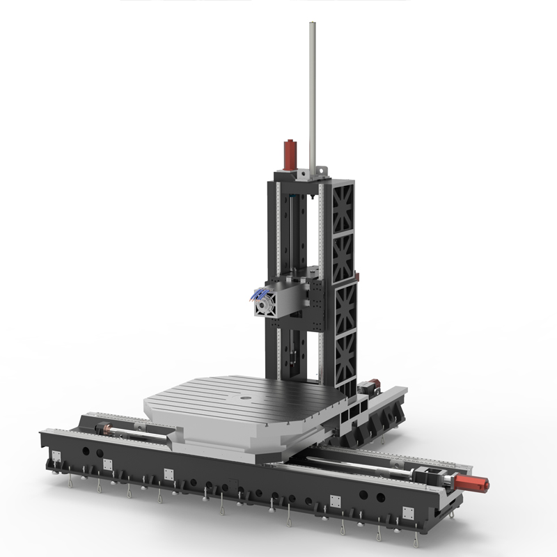
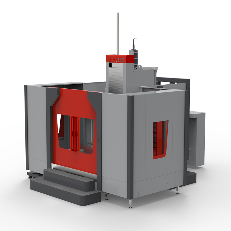
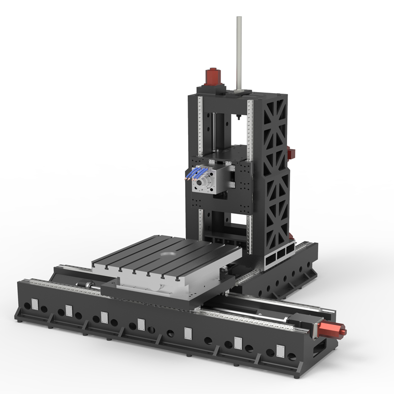
The heavy-cutting horizontal machining center is a horizontal machining center specially designed for heavy-duty cutting. It is typically used for machining large, heavy workpieces or machining tasks requiring high cutting forces. The following are the features and functions of heavy cutting horizontal machining centers:
1. High rigidity and stability: The structural design and material selection of the heavy-cutting horizontal machining center have high rigidity and stability, and can withstand large cutting forces and processing loads, ensuring the stability and accuracy of the processing process.
2. Powerful spindle and power system: The heavy-cutting horizontal machining center is equipped with a powerful spindle and power system, which can provide sufficient cutting capacity and speed range, and is suitable for heavy-duty cutting processing.
3. Large worktable and stroke: This type of machining center usually has a large worktable size and stroke, which can accommodate large workpieces and support complex machining operations.
4. Suitable for a variety of materials: Heavy cutting horizontal machining centers can process various metal materials, including steel, aluminum alloys, titanium alloys, etc., as well as some composite materials, with a wide range of applications.
5. High efficiency and productivity: Due to its powerful cutting capacity and large-size workbench, the heavy-cutting horizontal machining center can achieve high-efficiency and high-productivity processing, and is suitable for large-volume processing in industrial production. Task.
6. Automation and intelligent functions: Some heavy-cutting horizontal machining centers are equipped with automation devices and intelligent control systems, such as automatic tool changing systems, automatic workpiece clamping systems and CNC programming functions, to improve processing efficiency and operational convenience.
7. Precision machining capabilities: Although it is a heavy-duty cutting machining center, the heavy-cutting horizontal machining center still has certain precision machining capabilities and can meet the processing requirements of complex workpieces.
To sum up, the heavy-cutting horizontal machining center is a special equipment used for high-cutting tasks of large and heavy workpieces. It has strong cutting capabilities, stability and high efficiency, and is one of the important processing equipment in the manufacturing industry.
| Specifications/model | Unit | WB14B/C/D | WB18B/C/D | WB24B/C/D |
| Workbench specifications | ||||
| Rotary work surface dimensions | MM | 1400×1200 | 1800×1600 | 2400×2200 |
| Turntable structure (standard) | °C | 0.001 | 0.001 | 0.001 |
| Turntable structure (optional) | °C | 1/5/90 | 1/5/90 | 1/5/90 |
| Turntable load-bearing | T | 7 | 12 | 20 |
| Machine tool mechanism | / | Inverted T shape | Inverted T shape | Inverted T shape |
| Worktable left and right travel X mark/select | MM | 2000/2500 | 2500/3000 | 3000/4000 |
| Spindle box upper and lower stroke Y mark/select MM | 1000/1500 | 1500/2000 | 2000/2500 | |
| Column front and rear travel Z1 | MM | 1000 | 1000 | 1500 |
| Type B square ram front and rear travel Z2 | MM | 600 | 600 | 600 |
| Square ram specifications | MM | 360*360 | 360*360 | 360*360 |
| Maximum spindle speed/optional | RPM | 4000/6000 | 4000/6000 | 4000/6000 |
| C type boring bar front and rear travel Z2 | MM | 600 | 600 | 600 |
| Boring bar specifications | MM | 130 | 130 | 130 |
| Maximum spindle speed/optional | RPM | 1200/2000 | 1200/2000 | 1200/2000 |
| Distance from spindle end face to table center | MM | 200-1400 | 500-1700 | 600-2300 |
| Distance from spindle center to table surface | MM | 100-11/160000 | 100-1600/2100 | 100-2100/2600 |
| Workbench T-slot (slot width * number of slots) | / | 24*7 | 24*9 | 24*11 |
| Spindle content | ||||
| Spindle model/installation dimensions | MM | BT50/190 | BT50/190 | BT50/190 |
| Spindle motor | KW | 22KW | 22KW | 22KW |
| Maximum spindle speed/optional | RPM | 3000/4000 | 3000/4000 | 3000/4000 |
| Spindle drive | / | Variable speed gear transmission | Variable speed gear transmission | Variable speed gear transmission |
| Axis item content | ||||
| X-axis guide rail specifications/quantity | MM/N | Roller 55/2 | Roller 55/2 | Roller 55/2 |
| Y-axis guide rail specifications/quantity | MM/N | Roller 45/4 | Roller 45/4 | Roller 45/4 |
| Z-axis guide rail specifications/quantity | MM/N | Roller 55/2+hard rail | Roller 55/2+hard rail | Roller 55/2+hard rail |
| Three-axis ball screw specifications | MM | 63, 50, 63 | 63, 50, 63 | 63, 50, 63 |
| Square ram or boring bar ball screw specifications | MM | 40 | 40 | 40 |
| XY fast movement speed | M/MIN | 12, 12 | 12, 12 | 12, 12 |
| Z1/Z2 speed moving speed | M/MIN | 12, 20 | 12, 20 | 12, 20 |
| Three-axis motor connection method | / | direct connection | Reducer + direct connection | Reducer + direct connection |
| X, Y brake power | NM | 40, 40B | 40, 40B | 40, 40B |
| Z1, Z2 power | NM | 40, 22 | 40, 22 | 40, 22 |
| Spindle box balancing system | / | Nitrogen balance | Nitrogen balance | Nitrogen balance |
| air pressure | KG/MM | 6.5 | 6.5 | 6.5 |
| coolant capacity | L | 450 | 450 | 450 |
| Lubricating oil capacity | L | 4 | 4 | 4 |
| Oil and gas pressure system | ||||
| battery capacity | KW | 55 | 55 | 55 |
| Voltage floating | VAC | 380±5% | 380±5% | 380±5% |
| Phase | PHASE | 3 boxes 5 lines | 3 boxes 5 lines | 3 boxes 5 lines |
| air pressure | KG | 6.5-8 | 6.5-8 | 6.5-8 |
| Form factor | ||||
| Machine weight (approx.) | T | 22/26 | 26/30 | 33/37 |
| Machine length (front and rear) markings | MM | 4000 | 4500 | 5000 |
| Machine width (left and right) mark | MM | 6000 | 7000 | 8000 |
| Machine height (maximum) mark | MM | 4500 | 4500 | 4500 |
| Chip removal method | / | Twin screw/chain plate type | Twin screw/chain plate type | Twin screw/chain plate type |

 English
 日本語
日本語 한국어
한국어 Россия
  Français
 España
 عرب .
عرب .  Português
 Deutsch
 भारत
भारत Нидерланды
