- Recommended news
-
System composition of CNC horizontal machining center
2024-06-18
-
A method to solve the problem of spindle shaking in CNC lathes
2024-06-15
-
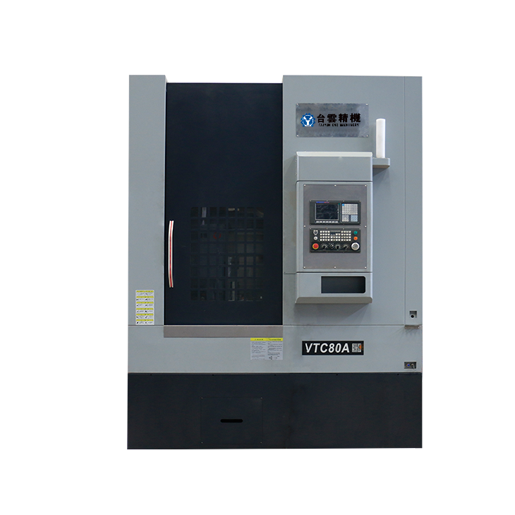
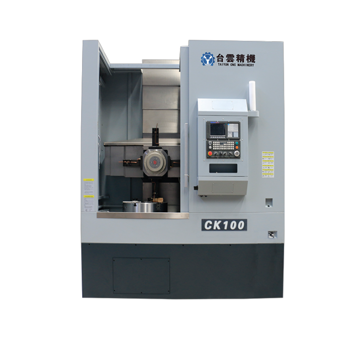
In which industry is the most widely used CNC vertical lathe?
2024-06-04
-
How to clamp the workpiece on a CNC vertical lathe?
2024-05-29
-
CNC milling machine machining center commonly used accessories
2024-05-25
-
Steps for adjusting the turret of a CNC vertical lathe
2024-05-22
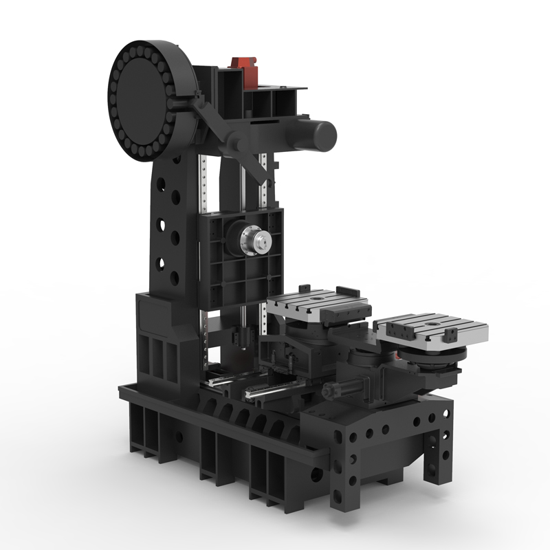
Horizontal machining center with low failure rate
To achieve a low failure rate of horizontal machining centers, the following measures can be taken:...
To achieve a low failure rate of horizontal machining centers, the following measures can be taken:
1. Regular maintenance: Regular maintenance of the horizontal machining center, including cleaning, lubrication, inspection of various components, etc., to ensure that the horizontal machining center is in good working condition and reduce the possibility of failure.
2. Use high-quality accessories: Horizontal machining centers use high-quality, reliable parts and accessories, such as spindles, servo motors, transmission systems, etc., to avoid failures caused by parts quality issues.
3. Strict operating procedures: The horizontal machining center formulates strict operating procedures and safe operating procedures to ensure that operators operate the equipment correctly and avoid failures caused by misoperation.
4. Regular inspection: Regularly conduct comprehensive inspections and evaluations of the horizontal machining center to identify potential problems and repair them in a timely manner to prevent the occurrence and expansion of faults.
5. Training operators: Provide professional training and skill improvement for horizontal machining center operators to improve their operating skills and troubleshooting capabilities and reduce failures caused by operating errors.
6. Monitoring system: The horizontal machining center installs a monitoring system to monitor the equipment in real time, detect abnormal situations in a timely manner and take measures to prevent the occurrence and expansion of faults.
7. Quality management: Strengthen the quality management system of the horizontal machining center, strictly control the quality during the production process, ensure that the parameters and performance of the machining center meet the requirements, and reduce the failure rate.
Through the above measures, the horizontal machining center can effectively reduce the failure rate of the horizontal machining center, improve the reliability and stability of the equipment, and ensure the normal operation of the production line and the improvement of production efficiency.
| Specifications/model | Unit | WA50 | WA63 | WA80 |
| Work content | ||||
| Installation turntable specifications (optional) | MM | 500*500 | 630*630 | 800*800 |
| Workbench indexing (standard) | N | 1 degree 1 minute | 1 degree 1 minute | 1 degree 1 minute |
| Customized workbench (optional) | N | Customize other graduations | Customize other graduations | Customize other graduations |
| Maximum rotation diameter of worktable | MM | 850 | 1150 | 1300 |
| X-axis travel | MM | 800 | 1100 | 1300 |
| Y-axis travel (headstock moves up and down) | MM | 550 | 750 | 900 |
| Z-axis travel | MM | 500 | 600 | 700 |
| Distance from spindle center to worktable | MM | 110-660 | 110-860 | 110-1010 |
| Distance from spindle end face to worktable center | MM | 250-650 | 210-710 | 300-900 |
| Workbench (slot width*number of slots) | MM | 3-14 | 5-14 | 5-14 |
| Threaded hole (optional) | MM | 24-M14 | 24-M14 | 24-M14 |
| Workbench load-bearing | KG | 600 | 800 | 1000 |
| Spindle and spindle box specifications | ||||
| Spindle taper hole | ISO | BT40-150 | BT50-150 | BT50-190 |
| Spindle speed | RPM | 8000 | 8000 | 8000 |
| Feeding system | ||||
| Shaft Ball Screw Specifications | MM | 40/40/40 | 40/40/40 | 40/40/40 |
| X-axis rapid movement speed | M/MIN | X:48 | X:32 | X:32 |
| Y-axis rapid movement speed | M/MIN | Y:48 | Y:32 | Y:32 |
| Z-axis rapid movement speed | M/MIN | Z:48 | Z:32 | Z:32 |
| X/Y/Z axis rail specifications | MM | Roller 35/45/45 | Roller 45/45/45 | Roller 45/45/45 |
| Motor connection method | / | Direct | Direct | Direct |
| Main motor parameters | KW | 11 | 11 | 15 |
| X-axis motor power | NM | X:22 | X:22 | X:22 |
| Y-axis motor power | NM | Y:22B | Y:22B | Y:22B |
| Z-axis motor power | NM | Z:22 | Z:22 | Z;30 |
| B-axis motor power | NM | B:8 | B:12 | B:12 |
| Axis positioning accuracy | MM | ±0.005 | ±0.005 | ±0.005 |
| Axis item repeat positioning accuracy | MM | ±0.003 | ±0.003 | ±0.003 |
| BPositioning accuracy | MM | 10" | 10" | 10" |
| B Repeat positioning accuracy | MM | 5" | 5" | 5" |
| Minimum move value | MM | 0.001 | 0.001 | 0.001 |
| Oil and gas pressure system | ||||
| air pressure | KG/MM | 6.5 | 6.5 | 6.5 |
| coolant capacity | L | 450 | 450 | 450 |
| Lubricating oil capacity L | L | 4 | 4 | 4 |
| Toolholder/Tool Magazine System (specify when ordering) | ||||
| Tool magazine structure | / | Top disc type | Top disc type | Top disc type |
| Number of tool magazines (optional) | T | twenty four | twenty four | twenty four |
| Tool changing time | MM | 3.2 | 3.2 | 3.2 |
| Maximum tool weight | KGS | 12 | 15 | 15 |
| Form factor | ||||
| Weight approx. | KG | 6.5 | 8.5 | 10 |
| Machine length | MM | 3500 | 3800 | 4000 |
| Machine width | MM | 2500 | 3000 | 3500 |
| Machine width (height) | MM | 2800 | 3000 | 3300 |
| Machine height (minimum) | MM | 2300 | 2500 | 2900 |
| Machine tool structure | / | Cross type | Cross type | Cross type |
| Chip removal method | / | back row | back row | back row |

 English
 日本語
日本語 한국어
한국어 Россия
  Français
 España
 عرب .
عرب .  Português
 Deutsch
 भारत
भारत Нидерланды
