English
 日本語
日本語 한국어
한국어 Россия
  Français
 España
 عرب .
عرب .  Português
 Deutsch
 भारत
भारत Нидерланды

- Recommended news
-
System composition of CNC horizontal machining center
2024-06-18
-
A method to solve the problem of spindle shaking in CNC lathes
2024-06-15
-
In which industry is the most widely used CNC vertical lathe?
2024-06-04
-
How to clamp the workpiece on a CNC vertical lathe?
2024-05-29
-
CNC milling machine machining center commonly used accessories
2024-05-25
-
Steps for adjusting the turret of a CNC vertical lathe
2024-05-22
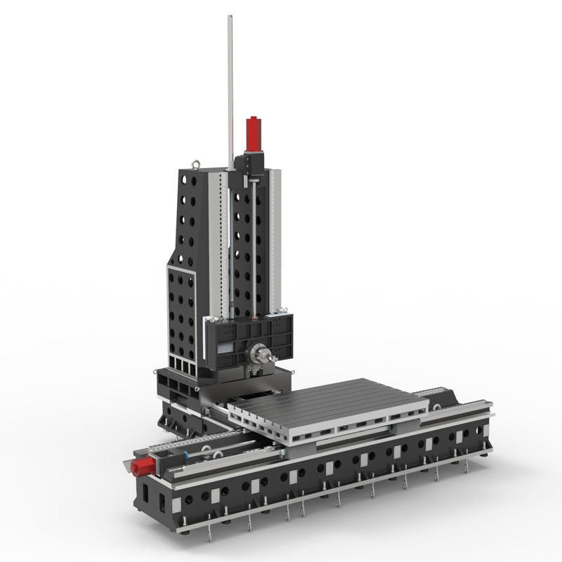
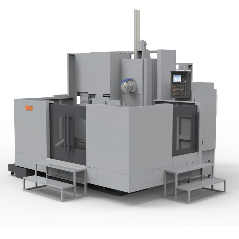
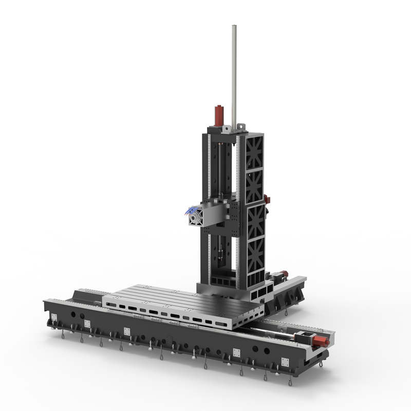
Horizontal machining center with reasonable layout
A horizontal machining center is a machining center equipment with a horizontally arranged workbench and spindle. Compared with a vertical machining center, the workpiece is processed in the horizontal direction....


A horizontal machining center is a machining center equipment with a horizontally arranged workbench and spindle. Compared with a vertical machining center, the workpiece is processed in the horizontal direction. This layout makes horizontal machining centers suitable for certain machining tasks and has some advantages in certain situations:
1. Uniform distribution of cutting force: Since the workpiece is processed in the horizontal direction in the horizontal machining center, the cutting force is relatively evenly distributed, which helps to reduce vibration and deformation during processing and improve processing quality.
2. Suitable for large workpieces: The horizontal machining center is suitable for processing large and heavy workpieces. Because the workpiece is placed on the workbench, it can effectively support the weight of the workpiece, reduce vibration and deformation, and improve processing accuracy.
3. Convenient for clamping and fixing: The workpiece of the horizontal machining center is placed on the horizontal workbench, which is convenient for clamping and fixing, and is easy to operate, which is beneficial to the stability and safety of the processing process.
4. More suitable for some special workpieces: Some special-shaped workpieces in horizontal machining centers, such as long strips, flat workpieces or workpieces with holes at the bottom, are more suitable for processing on horizontal machining centers.
5. Easy chip removal: During the processing of the horizontal machining center workpiece, the cutting chips can naturally fall from the bottom of the workpiece without affecting the processing process, improving the processing efficiency and the cleanliness of the working environment.
In general, horizontal machining centers have certain advantages when processing certain special-shaped workpieces, large workpieces, or when processing stability is required. However, the type of machining center needs to be selected based on the specific processing needs and workpiece characteristics. Reasonable choice.
| Specifications/Models | Unit | WY10 | WY15 | WY20 | WY25 | WY30 | WY40 |
| Work content | |||||||
| Work surface size | MM | 1200×1600 | 1700×800 | 2000×1200 | 2500×1400 | 3000×1400 | 4000×1400 |
| X-axis travel | MM | 1100 | 1600 | 2100 | 2600 | 3100 | 4200 |
| Y-axis spindle box up and down travel (standard/optional) | MM | 700/900 | 700/900 | 1000/1500 | 1000/1500 | 1500/2000 | 1500/2000 |
| Z-axis column front and rear travel (standard, optional) | MM | 800 | 800/1200 | 800/1200 | 800/1200 | 800/1200 | 800/1200 |
| Distance from spindle center to worktable | MM | 120-890 | 120-1120 | 120-1320 | 120-1820 | 120-1820 | 120-2120 |
| Distance from spindle end face to worktable center | MM | 130-1030 | 200-1200 | 400-1600 | 500-1700 | 500-1700 | 700-1700 |
| Workbench slot width + T slot | MM | 5-22 | 9-28 | 9-28 | 11-28 | 11-28 | 11-28 |
| Workbench load-bearing | KG | 1200 | 2500 | 3000 | 6000 | 10000 | 14000 |
| Spindle and spindle specifications | |||||||
| Spindle taper hole | ISO | BT50-190 | BT50-190 | BT50-190 | BT50-190 | BT50-190 | BT50-190 |
| Spindle speed | RPM | 4000/6000 | 4000/6000 | 4000/6000 | 4000/6000 | 4000/6000 | 4000/6000 |
| Type A boring bar specification diameter (optional) | MM | / | 110 | 110 | 130 | 130 | 130 |
| Boring bar stroke Z1 (optional) | MM | / | 550 | 550 | 550 | 550 | 550 |
| Type B square ram specifications square type (optional) | MM | / | / | 320 | 320 | 320 | 320 |
| Square ram stroke Z2 (optional) | MM | / | / | 600 | 600 | 600 | 600 |
| T-shaped workbench (slot width * number of slots) | / | 28*300 | / | 28*300 | 28*300 | 28*300 | 28*300 |
| Feeding system | |||||||
| Shaft Ball Screw Specifications | MM | 40/40/50 | 50/50/50 | 63/50/50 | 63/50/50 | 63/50/50 | 80/63/63 |
| XYZ axis rapid movement speed | M/MIN | 32.32.32 | 32.32.32 | 24.24.24 | 24.24.24 | 20.24.24 | 20.24.24 |
| X/Z axis wire gauge specifications | MM | Roller 55/55 | Roller 55/55 | Roller 55/55 | Roller 55/55 | Roller 55/55 | Roller 55/55 |
| Y-axis wire gauge specifications | MM | Roller 55 | Roller 55 | Roller 45*4 | Roller 45*4 | Roller 45*4 | Roller 45*4 |
| Motor connection method | / | Direct | Direct | Direct connection + reducer | Direct connection + reducer | Direct connection + reducer | Direct connection + reducer |
| Main motor parameter marking/selection | KW | 22/+reducer | 22/+reducer | 22/+reducer | 22/+reducer | 22/+reducer | 22/+reducer |
| Axis positioning accuracy | MM | ±0.005 | ±0.005 | ±0.005 | ±0.005 | ±0.005 | ±0.005 |
| Axis item repeat positioning accuracy | MM | ±0.003 | ±0.003 | ±0.003 | ±0.003 | ±0.003 | ±0.003 |
| Minimum move value | MM | 0.001 | 0.001 | 0.001 | 0.001 | 0.001 | 0.001 |
| Oil and gas pressure system | |||||||
| Spindle box balancing system (vertical installation) | / | gas balance | gas balance | gas balance | gas balance | gas balance | gas balance |
| air pressure | KG/MM | 6.5 | 6.5 | 6.5 | 6.5 | 6.5 | 6.5 |
| coolant capacity | L | 550 | 550 | 550 | 550 | 550 | 550 |
| Lubricating oil capacity L | L | 4 | 4 | 4 | 4 | 4 | 4 |
| Toolholder/Tool Magazine System (specify when ordering) | |||||||
| Tool magazine structure | / | Disc knife arm type | Disc knife arm type | Disc knife arm type | Disc knife arm type | Disc knife arm type | Disc knife arm type |
| Number of tool magazines (optional) | T | 24/32 | 24/32 | 24/32 | 24/32 | 24/32 | 24/32 |
| Knife inventory structure (optional) | / | Chain plate type tool magazine | Chain plate type tool magazine | Chain plate type tool magazine | Chain plate type tool magazine | Chain plate type tool magazine | Chain plate type tool magazine |
| Number of tool magazines | T | 40/50/60/80 | 40/50/60/80 | 40/50/60/80 | 40/50/60/80 | 40/50/60/80 | 40/50/60/80 |
| Tool changing time | MM | 5.2 | 5.2 | 5.2 | 5.2 | 5.2 | 5.2 |
| Maximum tool weight | KGS | 18 | 18 | 18 | 18 | 18 | 18 |
| Form factor | |||||||
| Weight approx. | T | 9 | 13/15 | 16/18 | 22/24 | 24/26 | 32/34 |
| Machine width | MM | 3000 | 4000 | 5000 | 6500 | 7500 | 9700 |
| Machine length | MM | 4500 | 5500 | 5800 | 6300 | 6300 | 7300 |
| Machine height (maximum) | MM | 4100 | 4300 | 5000 | 5500 | 5500 | 6000 |
| Machine tool mechanism | / | Inverted T shape | Inverted T shape | Inverted T shape | Inverted T shape | Inverted T shape | Inverted T shape |
| Chip removal method | / | Twin screw + chain plate | Twin screw + chain plate | Twin screw + chain plate | Twin screw + chain plate | Twin screw + chain plate | Twin screw + chain plate |