- Recommended news
-
System composition of CNC horizontal machining center
2024-06-18
-
A method to solve the problem of spindle shaking in CNC lathes
2024-06-15
-
In which industry is the most widely used CNC vertical lathe?
2024-06-04
-
How to clamp the workpiece on a CNC vertical lathe?
2024-05-29
-
CNC milling machine machining center commonly used accessories
2024-05-25
-
Steps for adjusting the turret of a CNC vertical lathe
2024-05-22
CNC gantry machining center
CNC gantry machining center is a CNC machine tool for high-precision processing of large and complex workpieces....
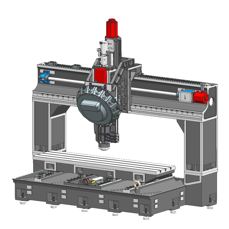
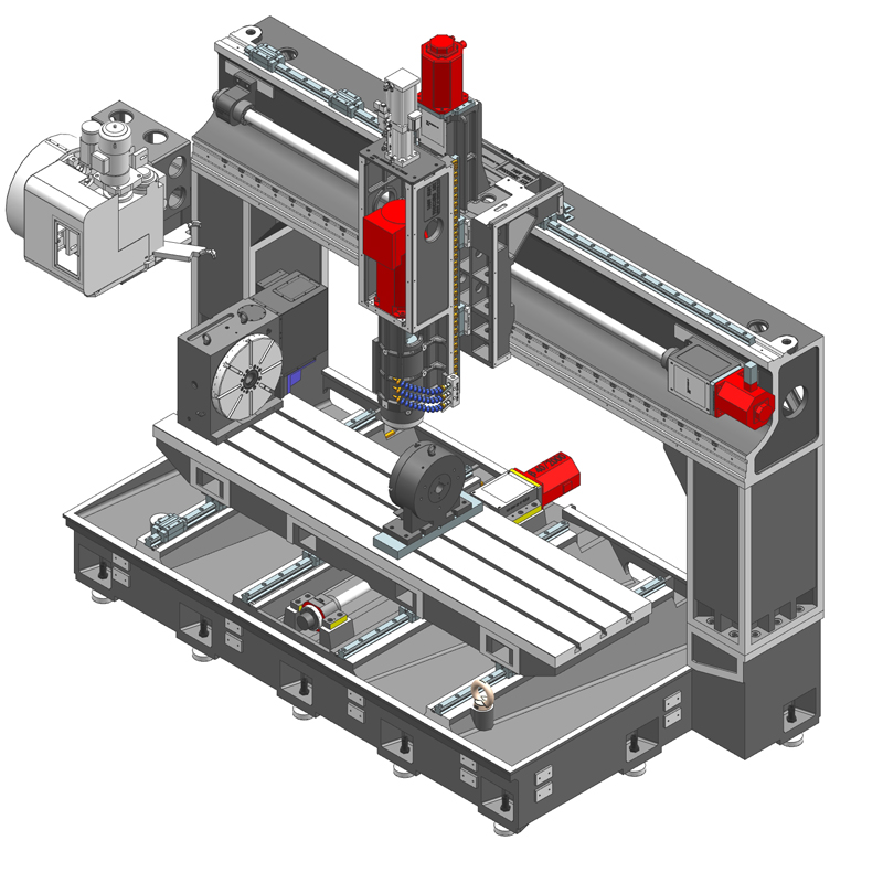
CNC gantry machining center is a CNC machine tool for high-precision processing of large and complex workpieces. The CNC gantry machining center adopts a gantry structure and has three axial movements of X, Y, and Z. It is suitable for milling, drilling, cutting and other processing operations on workpieces. The following are some features and applications of CNC gantry machining centers:
Features:
1. High rigidity structure: The CNC gantry machining center adopts a stable gantry structure, which has high rigidity and stability and can withstand heavy-load processing of large workpieces while maintaining high accuracy.
2. Multi-axis motion: CNC gantry machining centers usually have three axes of motion, X, Y, and Z, as well as possible rotation axes, etc. These axial movements of CNC gantry machining centers can realize multi-axis cutting and processing of complex workpieces.
3. High speed and high precision: The CNC gantry machining center is equipped with advanced servo control system and precision driving device, which can achieve high-speed processing and high-precision processing requirements.
4. Automated operation: The CNC gantry machining center adopts an automatic tool changing system and an automatic workpiece clamping device, which can realize automatic processing and improve production efficiency.
application:
1. Aerospace: CNC gantry machining centers are widely used in the aerospace field and are used to process complex workpieces such as aircraft parts and engine parts. CNC gantry machining centers have high processing accuracy and good reliability requirements.
2. Automobile manufacturing: CNC gantry machining centers are used in the automobile manufacturing industry to process automobile chassis, engine parts, body structures, etc., and can meet high processing accuracy and stability requirements.
3. Mold manufacturing: CNC gantry machining center can be used to manufacture workpieces such as molds, templates and models, and can perform complex three-dimensional processing and engraving processes to improve the quality and production efficiency of molds.
4. Ship manufacturing: CNC gantry machining center can be used to process large ship components and hull structures. It has high rigidity and stability and is adapted to the processing needs of large workpieces in ship manufacturing.
5. Railway transportation: In the field of railway transportation, CNC gantry machining centers are used in the manufacturing of high-speed train bodies and the processing of vehicle parts for rail transportation.
CNC gantry machining center is a powerful machine tool that is widely used in aerospace, automobile manufacturing, mold manufacturing and other industries. It can achieve high-precision complex machining tasks and improve production efficiency and product quality.
| Specifications/model | unit | SFA/T1512 | SFA/T2012 | SFA/T2016 | SFA/2512T | SFA/T2516 | SFA/T3012 | SFA/T3016 |
| Work content | ||||||||
| Workbench size (X-axis direction) | MM | 1500*1200 | 2000*12000 | 2000*16000 | 2500*1200 | 1500*1600 | 3000*1200 | 3000*1600 |
| X*Y axis travel | MM | 1600*1200 | 2100*120 | 2100*1600 | 2600*1200 | 2600*1600 | 3100*1200 | 3100*1600 |
| Gantry width | MM | 1650 | 2230 | 2230 | 2730 | 2730 | 3230 | 3230 |
| Z-axis travel (up and down) | MM | 550 | 550 | 550 | 550 | 550 | 550 | 550 |
| Distance from spindle nose to work surface | MM | 170-720 | 170-720 | 170-720 | 170-720 | 170-720 | 170-720 | 170-720 |
| Maximum load of workbench | T | 1 | 1 | 1 | 1.5 | 1.5 | 2 | 2 |
| Spindle content type A | ||||||||
| Spindle specifications | BT | BT40 direct connection | BT40 direct connection | BT40 direct connection | BT40 direct connection | BT40 direct connection | BT40 direct connection | BT40 direct connection |
| Spindle transmission structure | / | Mechanical spindle | Mechanical spindle | Mechanical spindle | Mechanical spindle | Mechanical spindle | Mechanical spindle | Mechanical spindle |
| Spindle speed | RPM | 12000 | 12000 | 12000 | 12000 | 12000 | 12000 | 12000 |
| Optional model speed of electric spindle | HSK | A63 | A63 | A63 | A63 | A63 | A63 | A63 |
| Spindle speed | RPM | 18000 | 18000 | 18000 | 18000 | 18000 | 18000 | 18000 |
| Tool magazine structure A (specify when ordering) | PCS | Robotic arm disc | Robotic arm disc | Robotic arm disc | Robotic arm disc | Robotic arm disc | Robotic arm disc | Robotic arm disc |
| Tool magazine capacity | BT40-24T | BT40-24T | BT40-24T | BT40-24T | BT40-24T | BT40-24T | BT40-24T | |
| Tool changing time T-T | MM | 2.2 | 2.2 | 2.2 | 2.2 | 2.2 | 2.2 | 2.2 |
| Tool magazine structure T (specify when ordering) | / | Clamp type | Clamp type | Clamp type | Clamp type | Clamp type | Clamp type | Clamp type |
| Tool magazine capacity | T | BT40-16T | BT40-16T | BT40-16T | BT40-16T | BT40-16T | BT40-16T | BT40-16T |
| Tool changing time T-T | MM | 1.8 | 1.8 | 1.8 | 1.8 | 1.8 | 1.8 | 1.8 |
| Maximum tool weight | KG | 8 | 8 | 8 | 8 | 8 | 8 | 8 |
| Feed content | ||||||||
| G00 rapid traverse (three axes) | m/min | 36.48.48 | 36.48.48 | 36.48.48 | 36.48.48 | 36.48.48 | 36.48.48 | 36.48.48 |
| G01 cutting feed | mm/min | 1-30000 | 1-30000 | 1-30000 | 1-30000 | 1-30000 | 1-30000 | 1-30000 |
| Servo motor specifications | NM | 22.22.22B | 22.22.22B | 22.22.22B | 22.22.22B | 22.30.22B | 30.30.22B | 30.30.22B |
| Servo motor speed | RPM | 3000 | 3000 | 3000 | 3000 | 2000 | 3000 | 2000 |
| X.Y.Z motor connection method | / | Direct | Direct | Direct | Direct | Direct | Direct | Direct |
| X.Y.Z axis ball screw specifications | MM | 50.50.40 | 50.50.40 | 50.50.40 | 50.50.40 | 50.50.40 | 50.50.40 | 50.50.40 |
| Y-axis rack (optional) specifications | ||||||||
| X-axis rail specifications | MM | 45 ball | 45 ball | 45 ball | 45 ball | 45 ball | 45 ball | 45 ball |
| Y axis rail specifications | MM | 45 balls*2 | 45 balls*4 | 45 balls*4 | 45 balls*4 | 45 balls*4 | 45 balls*4 | 45 balls*4 |
| Z axis rail specifications | MM | 35 ball | 35 ball | 35 ball | 35 ball | 35 ball | 35 ball | 35 ball |
| Precise shaft positioning | MM | ±0.01 | ±0.01 | ±0.01 | ±0.01 | ±0.01 | ±0.01 | ±0.01 |
| Repeatable positioning precision | MM | ±0.005 | ±0.005 | ±0.005 | ±0.005 | ±0.005 | ±0.005 | ±0.005 |
| Minimum move value | MM | 0.001 | 0.001 | 0.001 | 0.001 | 0.001 | 0.001 | 0.001 |
| Oil and gas pressure system | ||||||||
| air pressure | KG/MM | 6.5 | 6.5 | 6.5 | 6.5 | 6.5 | 6.5 | 6.5 |
| Bed block height | MM | 40 | 40 | 40 | 40 | 40 | 40 | 40 |
| Lubricating oil capacity | L | 4 | 4 | 4 | 4 | 4 | 4 | 4 |
| battery capacity | KW | 30 | 30 | 30 | 30 | 30 | 30 | 30 |
| coolant capacity | L | 260 | 260 | 300 | 260 | 300 | 260 | 300 |
| Form factor | ||||||||
| Machine weight (approx.) | T | 9 | 10 | 12 | 12 | 14 | 14 | 17 |
| Machine length (front and rear) | MM | 3000 | 3500 | 4200 | 3500 | 4200 | 3500 | 4200 |
| Machine width (left and right) | MM | 3000 | 3500 | 3500 | 4000 | 4000 | 4500 | 4500 |
| Machine height (maximum) | MM | 3500 | 3500 | 3500 | 3500 | 3500 | 3500 | 3500 |
| Machine height (minimum) | MM | 3300 | 3300 | 3300 | 3300 | 3300 | 3300 | 3300 |
| Chip removal method (optional) | / | High voltage rear row | High voltage rear row | High voltage rear row | High voltage rear row | High voltage rear row | High voltage rear row | High voltage rear row |

 English
 日本語
日本語 한국어
한국어 Россия
  Français
 España
 عرب .
عرب .  Português
 Deutsch
 भारत
भारत Нидерланды
