- Recommended news
-
System composition of CNC horizontal machining center
2024-06-18
-
A method to solve the problem of spindle shaking in CNC lathes
2024-06-15
-
In which industry is the most widely used CNC vertical lathe?
2024-06-04
-
How to clamp the workpiece on a CNC vertical lathe?
2024-05-29
-
CNC milling machine machining center commonly used accessories
2024-05-25
-
Steps for adjusting the turret of a CNC vertical lathe
2024-05-22
CNC machining center parts processing
CNC machining centers are mainly used to process various complex-shaped parts, which can achieve high-precision and high-efficiency processing....
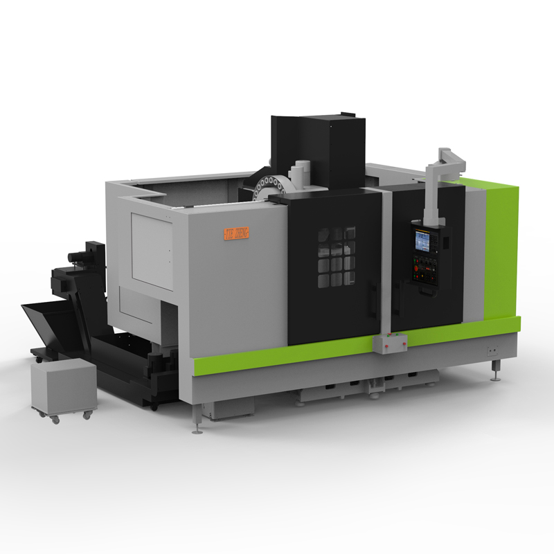
CNC machining centers are mainly used to process various complex-shaped parts, which can achieve high-precision and high-efficiency processing. In CNC machining centers, parts processing usually includes the following steps:
1. Design and programming: First, the CNC machining center uses CAD/CAM software to design the parts and program the processing paths according to the design requirements of the parts. During the programming process, factors such as machining technology, tool selection, cutting parameters, etc. are considered to generate CNC programs.
2. Material preparation: The CNC machining center prepares corresponding materials according to the material requirements of the parts, such as metal materials, plastic materials, etc. Ensure that the material quality of the CNC machining center meets the requirements and that the original workpiece is cut or forged according to the design size.
3. Clamping and fixing: The original workpiece is fixed on the workbench of the CNC machining center, usually using a clamp or fixture system to ensure the stability and accuracy of the CNC machining center workpiece during processing.
4. Tool selection and installation: According to the requirements in the programming program, select the appropriate tool for processing. Install the tool and adjust the tool position to ensure that the processing path of the tool and the workpiece matches, and to ensure safety and stability during the processing.
5. Processing operations: Start the CNC machining center and perform processing operations according to the pre-programmed processing paths and parameters. The CNC system controls each motion axis of the machining center to implement cutting, milling, drilling and other processing operations, and gradually completes the processing of parts.
6. Quality inspection: After the CNC machining center completes the processing, the parts will be inspected for quality, including dimensional inspection, surface quality inspection, etc. Ensure parts meet design requirements and customer needs and make necessary trims or adjustments.
7. Surface treatment and subsequent processing: The CNC machining center performs surface treatment according to the requirements of the parts, such as polishing, spraying, plating, etc. If the part requires further processing or assembly, subsequent processing or assembly operations can be performed.
Through the above steps, CNC machining centers can process various spare parts efficiently and accurately to meet the needs of different industries.
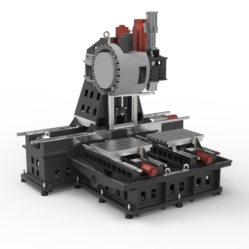
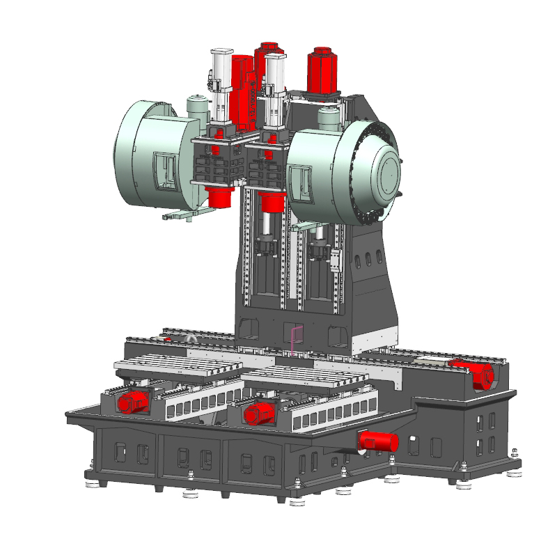
| Specifications/model | unit | VS650 | VS950 |
| Work content | |||
| working desk size | MM | 650*500 | 900*500 |
| Number of workbenches | N | 2 | 2 |
| X-axis travel (left and right) | MM | 1600 | 2200 |
| Y-axis travel (front and rear) | MM | 550 | 550 |
| Z-axis travel (up and down) | MM | 500 | 500 |
| Distance from spindle nose to work surface | MM | 150-650 | 150-650 |
| Distance from spindle center to column track surface | MM | 700 | 700 |
| Maximum load-bearing capacity of workbench | KG | 500 | 1000 |
| Spindle specifications | |||
| Spindle transmission structure (standard configuration) | / | Belt type | Belt type |
| Spindle speed | RPM | 8000 | 8000 |
| Spindle transmission structure (standard configuration) | / | direct connection | direct connection |
| Spindle speed | RPM | 12000 | 12000 |
| Spindle power | KW | 11 | 11 |
| Spindle bore taper | BT | BT10 | BT40 |
| Feed content | |||
| G00 rapid traverse (three axes) | M/MIN | 32/48/32 | 32/48/32 |
| G01 cutting feed | MM/MIN | 1-10000 | 1-10000 |
| Servo motor specifications | NM | 22/12/22B | 22/12/22B |
| Servo motor speed | RPM | 3000 | 3000 |
| XYZ motor connection method | / | Direct | 直联 |
| Ball screw specifications | MM | 4016/5012 | 4016/5012 |
| X-axis rail specifications | MM | 45 roller | 45 roller |
| Y axis rail specifications | MM | 35 roller | 45 roller |
| Z axis rail specifications | MM | 35 roller | 45 roller |
| Precise shaft positioning | MM | ±0.005/300 | ±0.005/300 |
| Repeatable positioning precision | MM | ±0.003/300 | ±0.003/300 |
| Minimum move value | MM | 0.001 | 0.001 |
| Tool magazine system | |||
| Tool magazine structure | / | Knife arm type | Knife arm type |
| Tool magazine capacity | PCS | 24 | 24 |
| Tool changing time | MIN | 2.2 | 2.2 |
| Maximum tool weight | KG | 8 | 8 |
| Oil and gas pressure system | |||
| air pressure | KG/MM | 6.5 | 6.5 |
| Lubricating oil capacity | L | 4 | 4 |
| battery capacity | KW | 30 | 40 |
| coolant capacity | L | 250 | 350 |
| Form factor | |||
| Machine weight (approx.) | T | 9 | 11 |
| Machine length (front and rear) | MM | 2700 | 2700 |
| Machine width (left and right) | MM | 3800 | 4200 |
| Machine height (maximum) | MM | 2900 | 2900 |
| Machine height (minimum) | MM | 2300 | 2300 |
| Chip removal method (optional) | / | single chain plate | single chain plate |
| Chip removal method (optional) | / | Twin screw | Twin screw |

 English
 日本語
日本語 한국어
한국어 Россия
  Français
 España
 عرب .
عرب .  Português
 Deutsch
 भारत
भारत Нидерланды
