- Recommended news
-
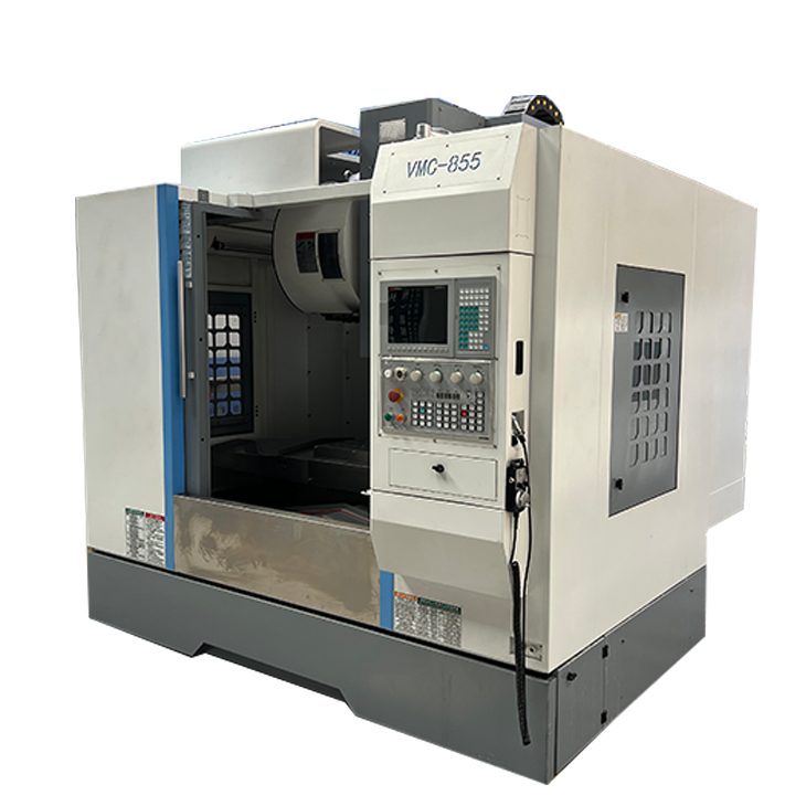
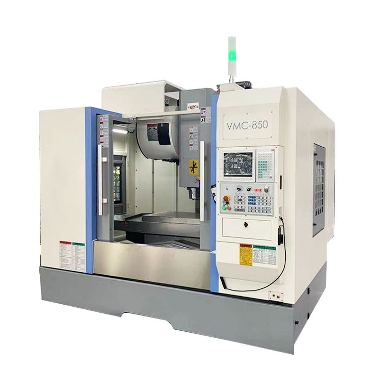
System composition of CNC horizontal machining center
2024-06-18
-
A method to solve the problem of spindle shaking in CNC lathes
2024-06-15
-
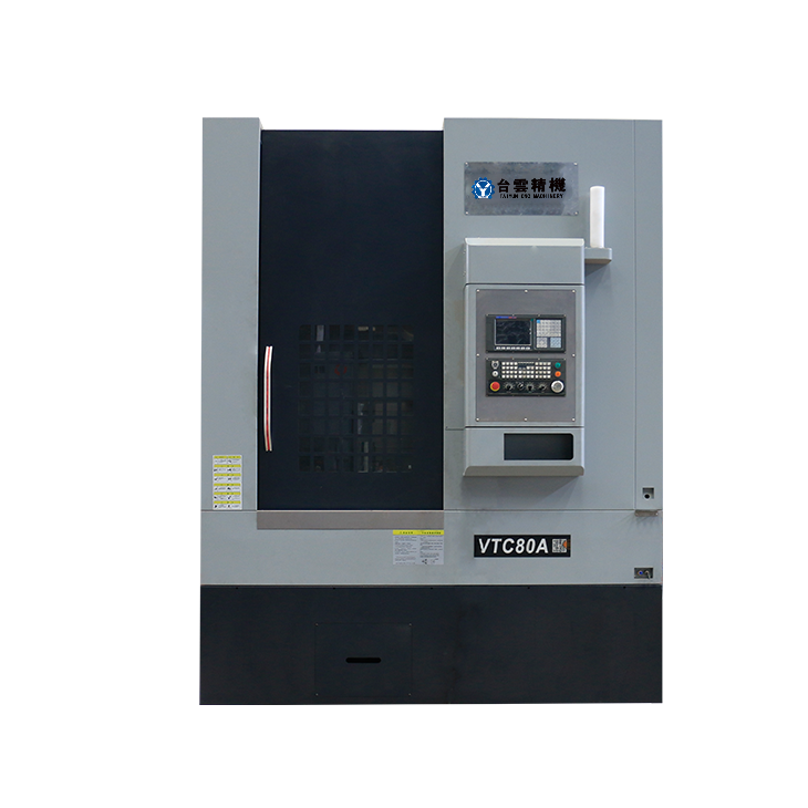
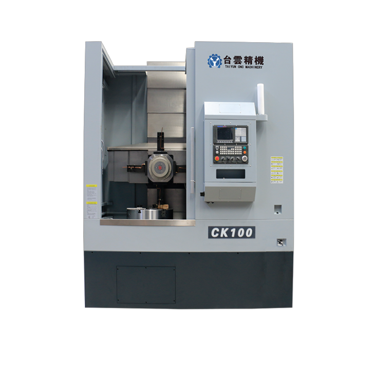
In which industry is the most widely used CNC vertical lathe?
2024-06-04
-
How to clamp the workpiece on a CNC vertical lathe?
2024-05-29
-
CNC milling machine machining center commonly used accessories
2024-05-25
-
Steps for adjusting the turret of a CNC vertical lathe
2024-05-22
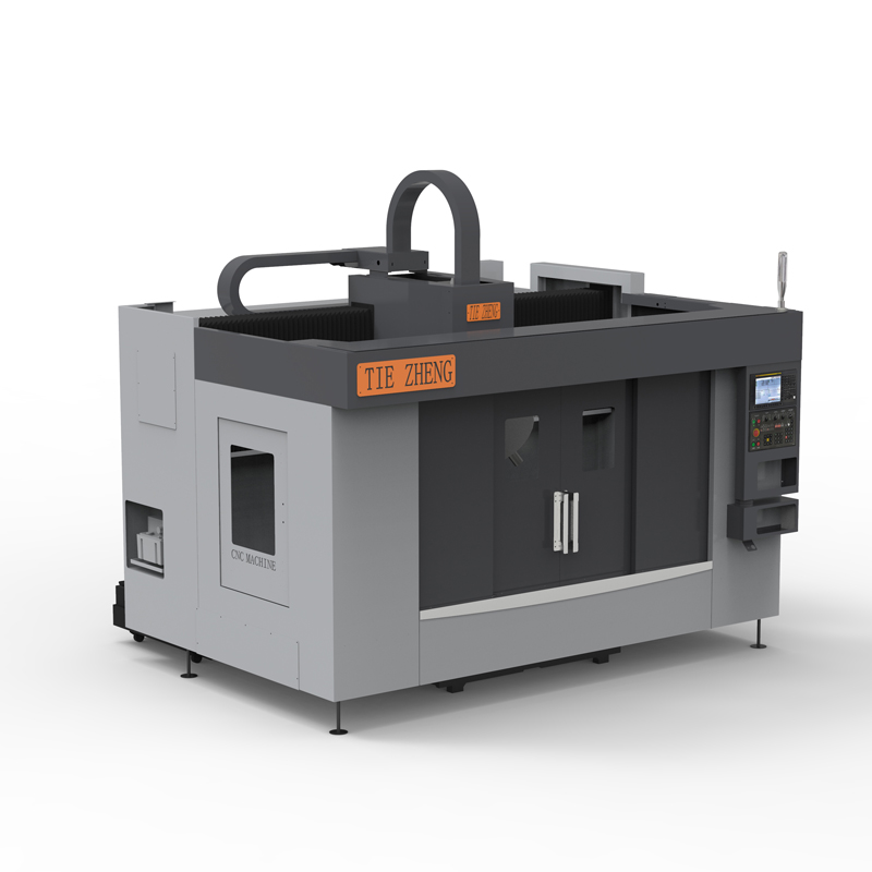
Light gantry machining center
The lightweight gantry machining center is a CNC machine tool suitable for processing large parts, especially in the fields of mold manufacturing, aviation, automobiles and heavy industry....
The lightweight gantry machining center is a CNC machine tool suitable for processing large parts, especially in the fields of mold manufacturing, aviation, automobiles and heavy industry. The lightweight gantry machining center has a larger workbench and higher processing range, providing greater processing flexibility and efficiency. The following is a brief introduction to several key features of the lightweight gantry machining center:
1. Structural features:
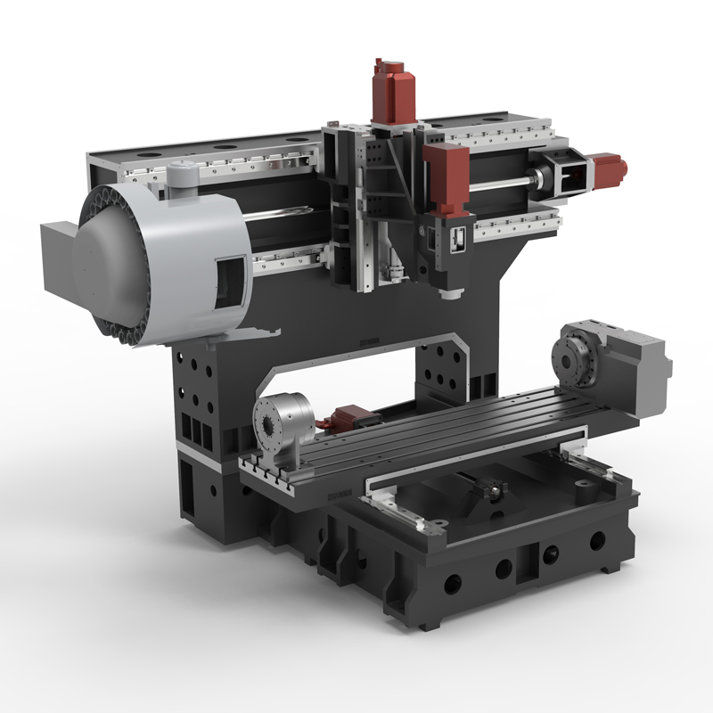
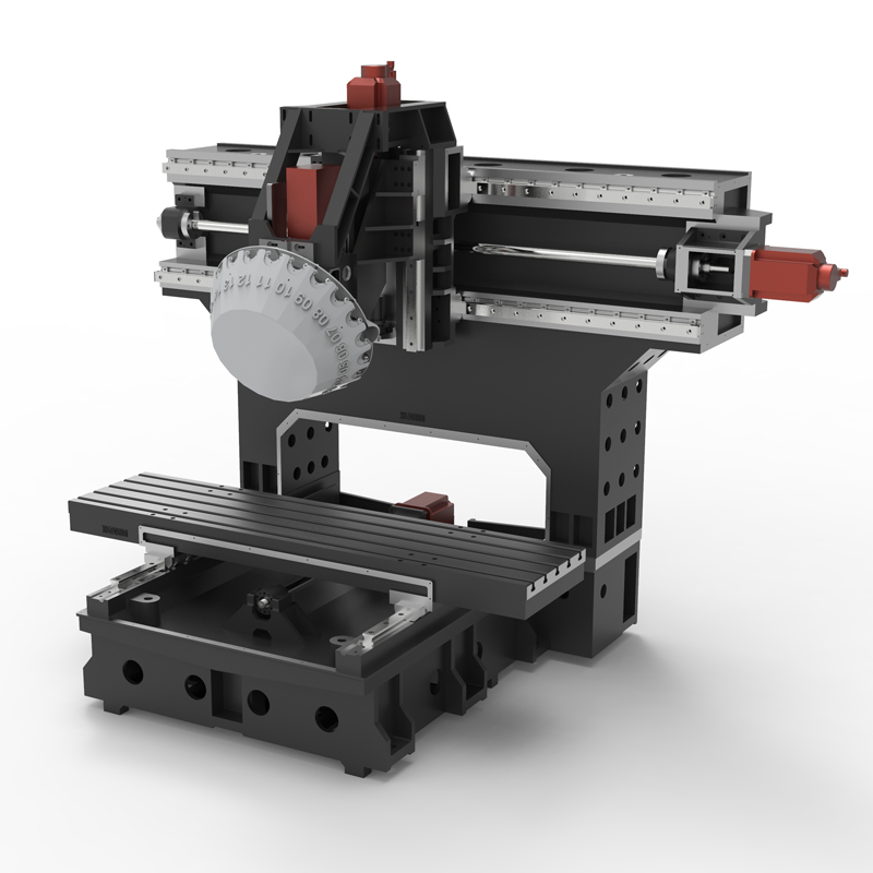
Gantry structure: The light gantry machining center adopts a gantry structure, that is, two columns support a cross beam, forming a "door"-shaped frame, and the workbench moves under this frame. This structure provides good rigidity and stability and is ideal for processing large or heavy workpieces.
High dynamic performance: In order to meet the needs of high-speed and high-precision machining, lightweight gantry machining centers are usually equipped with high-performance servo motors and drive systems, as well as high-precision guide rails and screw rods to ensure the accuracy of machine tools during high-speed operation. and stability.
2. Processing capacity:
Large-size workpiece processing: Gantry machining centers are particularly suitable for processing large-size workpieces, such as aerospace parts, molds, and automobile parts. The large workbench and sufficient processing space of the lightweight gantry machining center make the processing of large-size workpieces possible.
Multi-axis machining: Some lightweight gantry machining centers may be equipped with a rotary table or multi-axis head, which can perform five-axis machining of complex shapes, improving processing efficiency and processing accuracy.
3.Application fields:
Due to its ability to process large-sized workpieces, lightweight gantry machining centers are widely used in mold manufacturing, aerospace, automobile manufacturing, heavy industry, and other industries that require processing of large or complex workpieces.
4.Technical parameters and options:
When selecting a light gantry machining center, you should consider its workbench size, maximum load-bearing weight, spindle speed, processing range (X/Y/Z axis travel), accuracy requirements and other technical parameters to ensure that the selected equipment can meet specific processing needs. .
In short, the lightweight gantry machining center has become one of the important processing equipment in modern manufacturing industry with its unique structural advantages, high processing efficiency and wide range of applications.
| Specifications/model | unit | STA/T1350 | STA/T1650 | STA/T2050 |
| Workbench specifications | ||||
| Workbench size (X-axis direction) | MM | 1600*500 | 1900*500 | 2100*500 |
| X*Y axis travel (left and right) | 1300*500 | 1600*500 | 2000*500 | |
| Distance from spindle nose to work surface | 150-500 | 150-500 | 150-500 | |
| Z-axis heightening (optional) | 300-650 | 300-650 | 300-650 | |
| Maximum load-bearing capacity of workbench | KG | 1300 | 1600 | 2000 |
| Spindle specifications | ||||
| Spindle transmission structure (T type) | / | direct connection | direct connection | direct connection |
| Spindle speed | RPM | 20000 | 20000 | 20000 |
| Spindle horsepower | KW | 5.5 | 5.5 | 5.5 |
| Spindle bore taper | AT | BT30 | BT30 | BT30 |
| Tool changing time T-T | MIN | 1.8 | 1.8 | 1.8 |
| Maximum tool weight | KGS | 6 | 6 | 6 |
| Spindle transmission structure (Type A) | / | direct connection | direct connection | direct connection |
| Spindle speed | RPM | 12000 | 12000 | 12000 |
| Spindle horsepower | KW | 5.5 | 5.5 | 5.5 |
| Spindle inner hole dimensions | AT | BT30 | BT30 | BT30 |
| Tool changing time T-T | MIN | 2.2 | 2.2 | 2.2 |
| Maximum tool weight | KGS | 8 | 8 | 8 |
| Feed content | ||||
| G00 rapid traverse (X/Y/Z) | M/MIN | 32/48/48 | 32/48/48 | 32/48/48 |
| G01 rapid feed | M/MIN | 1-10000 | 1-10000 | 1-10000 |
| Servo motor specifications | NM | 22/22/22B | 22/22/22B | 22/22/22B |
| Servo motor speed | RPM | 2000/3000 | 2000/3000 | 2000/3000 |
| X.Y.Z motor connection method | / | Direct | Direct | Direct |
| Ball screw specifications | MM | 40/40/32 | 40/40/32 | 50/40/32 |
| X-axis rail specifications | MM | 45 ball | 45 ball | 45 ball |
| Y axis rail specifications | MM | 45 ball | 45 ball | 45 ball |
| Z axis rail specifications | MM | 35 ball | 35 ball | 35 ball |
| Precise shaft positioning | MM | ±0.01 | ±0.01 | ±0.01 |
| Repeatable positioning precision | MM | ±0.005 | ±0.005 | ±0.005 |
| Minimum move value | MM | 0.001 | 0.001 | 0.001 |
| Oil and gas pressure system | ||||
| air pressure | KG | 6.5 | 6.5 | 6.5 |
| Lubricating oil capacity | L | 4 | 4 | 4 |
| battery capacity | KW | 25 | 25 | 25 |
| coolant capacity | L | 320 | 320 | 320 |
| Form factor | ||||
| Machine weight (approx.) | KG | 7000 | 8500 | 10000 |
| Machine length (front and rear) | MM | 2500 | 2500 | 2500 |
| Machine width (left and right) | MM | 2300 | 2600 | 3200 |
| Machine height (maximum) | MM | 2500 | 2500 | 2500 |
| Machine height (minimum) | MM | 2200 | 2200 | 2200 |
| Chip removal method | / | backlash | backlash | backlash |

 English
 日本語
日本語 한국어
한국어 Россия
  Français
 España
 عرب .
عرب .  Português
 Deutsch
 भारत
भारत Нидерланды
