- Recommended news
-
System composition of CNC horizontal machining center
2024-06-18
-
A method to solve the problem of spindle shaking in CNC lathes
2024-06-15
-
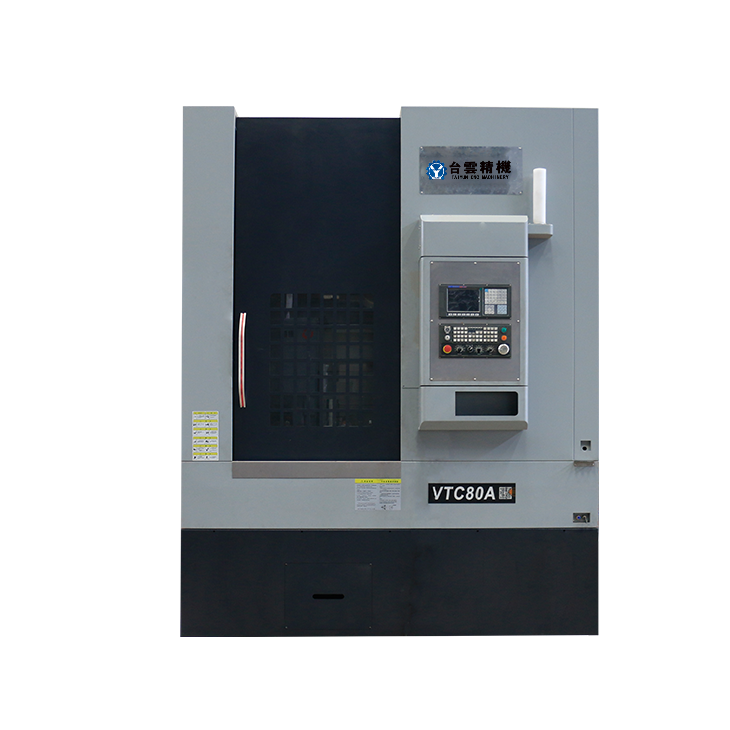
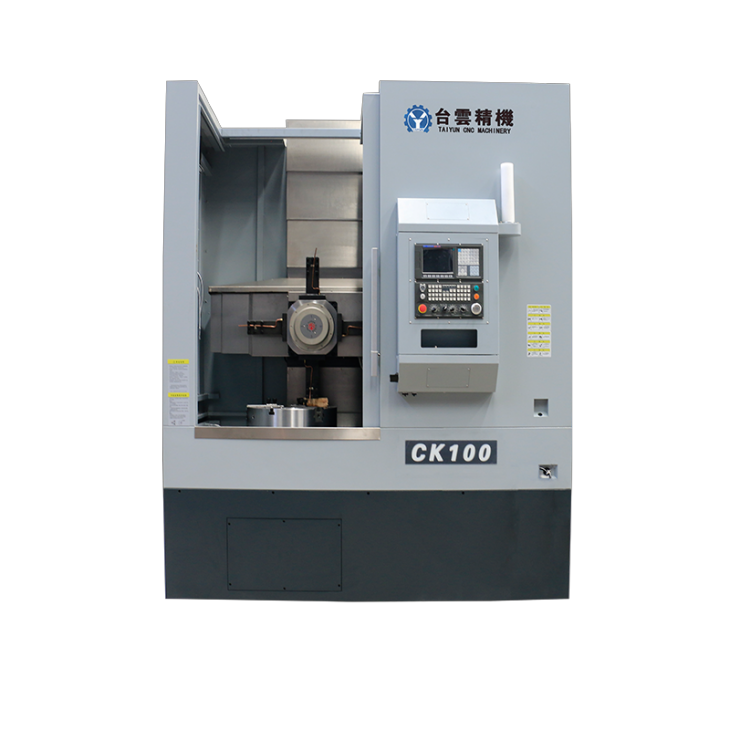
In which industry is the most widely used CNC vertical lathe?
2024-06-04
-
How to clamp the workpiece on a CNC vertical lathe?
2024-05-29
-
CNC milling machine machining center commonly used accessories
2024-05-25
-
Steps for adjusting the turret of a CNC vertical lathe
2024-05-22
Machining center system options
Choosing a machining center system configuration often depends on specific machining needs, budget, and the types of materials and parts being machined....
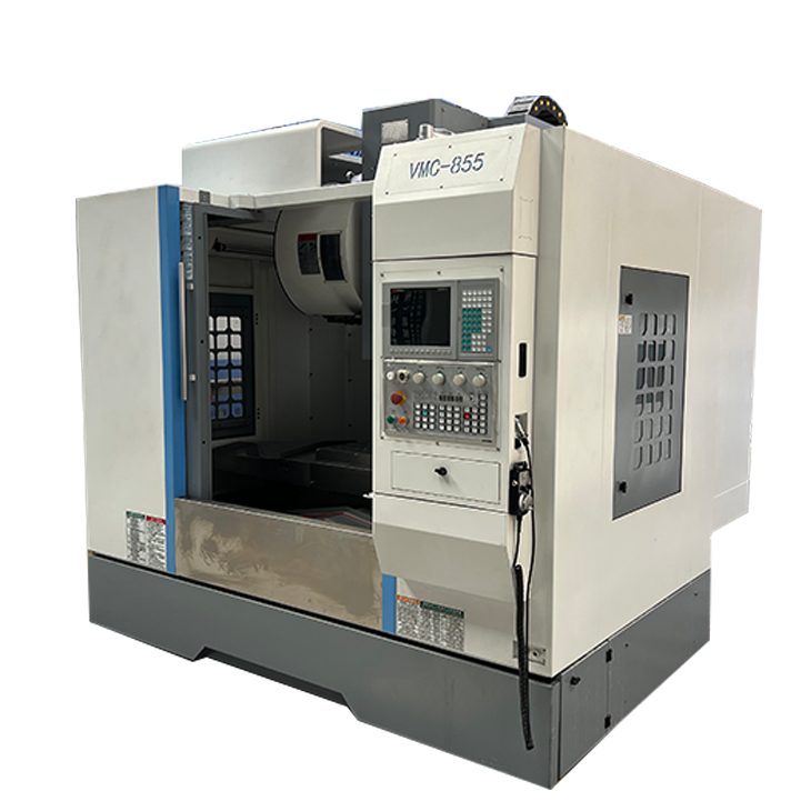
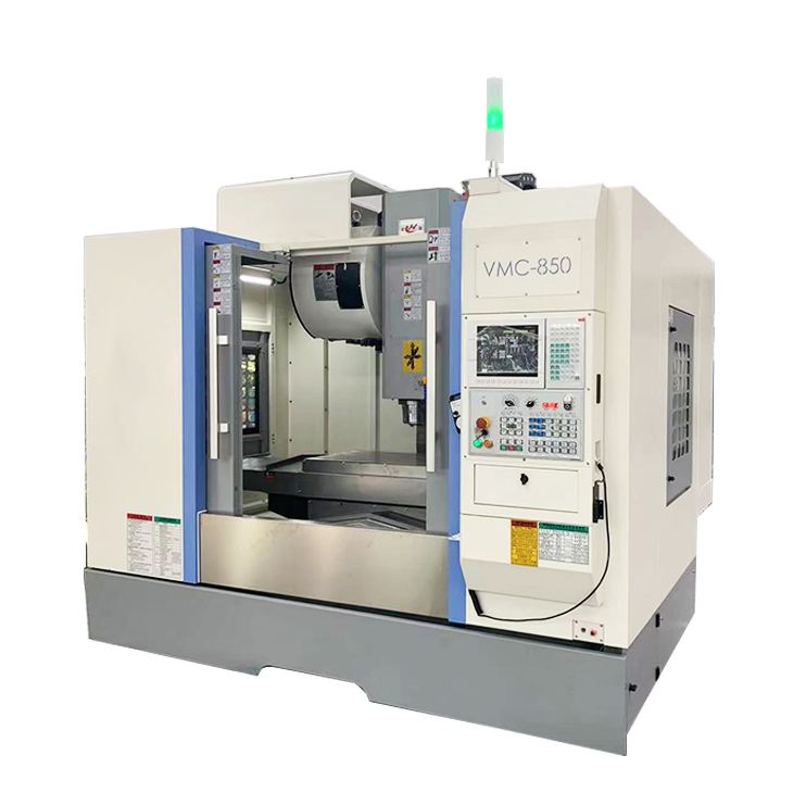
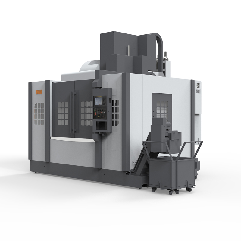
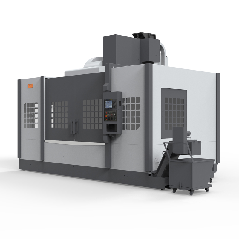
Choosing a machining center system configuration often depends on specific machining needs, budget, and the types of materials and parts being machined. Here are some common options:
1. CNC system: The CNC system of the machining center is a key component for controlling the operation of the machining center. You can choose CNC systems of different brands and models, such as Siemens, Fanuc, Mitsubishi, etc., and choose the appropriate control system according to your needs.
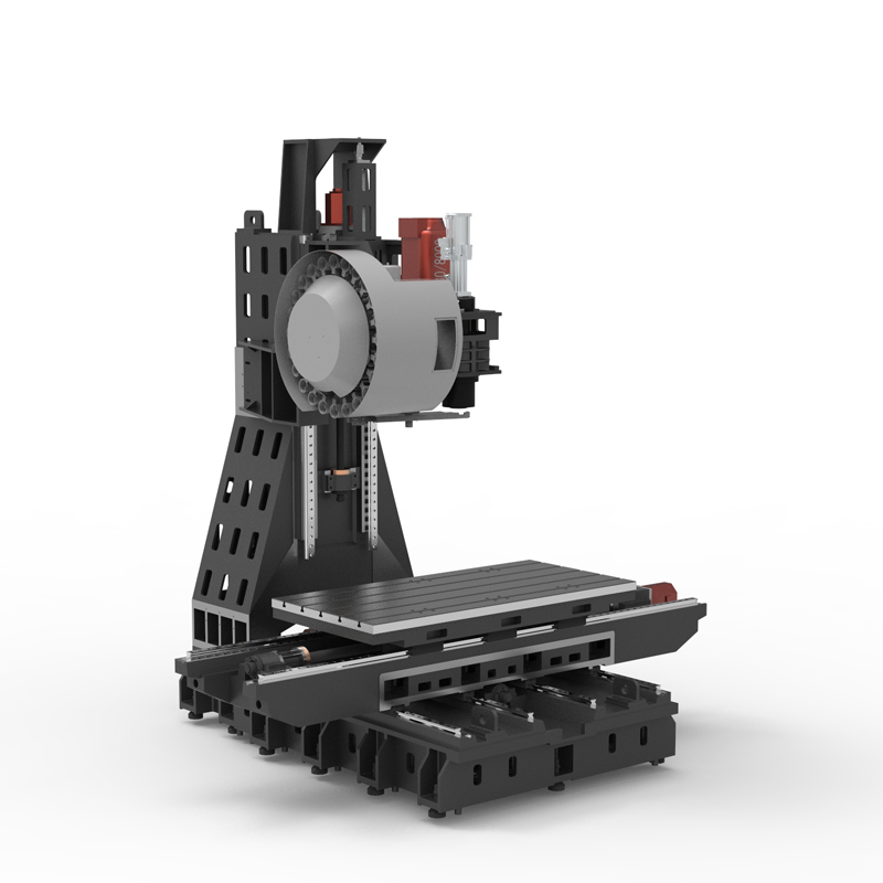
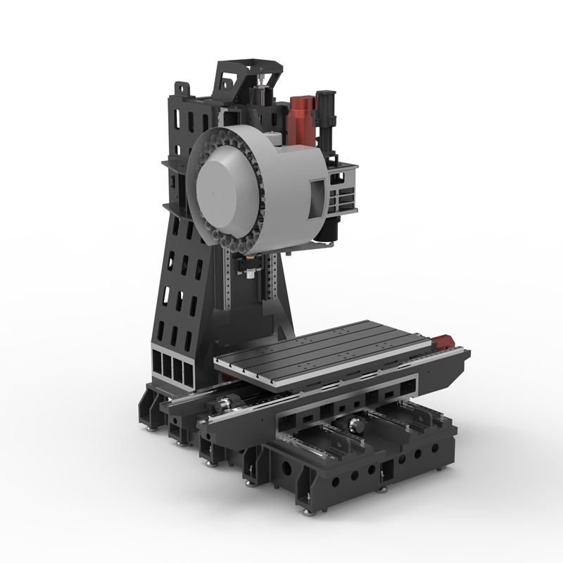
2. Spindle type: The machining center spindle is the core component of the machining center. You can choose different types of spindles, including high-speed spindles, high-torque spindles, direct-drive spindles, etc. Choose the appropriate spindle type according to the processing requirements and materials.
3. Tool library and tool changing device: The tool library and tool changing device of the machining center affect the flexibility and efficiency of the machining center. You can choose tool libraries of different specifications and capacities, as well as automatic tool changing devices, to improve processing efficiency.
4. Feed system: The feed system of the machining center affects the processing speed and accuracy of the machining center. Feed systems of different types and accuracy can be selected, such as linear guide rails, ball screws, etc.
5. Lubrication and cooling system: The lubrication and cooling system of the machining center has an important impact on the processing quality and tool life. You can choose lubrication and cooling systems of different types and performances, such as spray cooling, tool cooling, etc.
6. Workpiece clamping device: The machining center selects appropriate workpiece clamping devices, such as mechanical clamps, pneumatic clamps, hydraulic clamps, etc., according to the type and shape of the parts being processed.
7. Processing scope: Consider the processing range of the machining center, including processing size, processing depth, processing accuracy, etc., and select the appropriate processing range according to the processing needs.
8. Accessories and accessories: The machining center can also choose other accessories and accessories as needed, such as automatic workpiece measuring devices, workpiece surface treatment devices, etc., to meet specific processing needs.
To sum up, choosing the configuration of a machining center system should take into account processing needs, budget and performance requirements to ensure efficient and high-quality processing.
| Specifications/model | unit | V966 | V1160 | V1168 | V1270 | V1377 | V1387 | V1380C | V1680C | V2010C |
| Work content | ||||||||||
| working desk size | MM | 1100×700 | 1200×600 | 1200×600 | 1300×700 | 1400×7010 | 1400×800 | 1400×800 | 1700×800 | 2100×1000 |
| Workbench travel (X/Y/Z) | MM | 900×600×600 | 1100×600×600 | 1100×600×800 | 1200×700×600 | 1300×700×700 | 1300×800×700 | 1300×800×70 | 1600×800×700 | 2000×1000×800 |
| Distance from spindle nose to work surface | MM | 150-750 | 120-720 | 120-920 | 120-720 | 120-820 | 120-820 | 150-850 | 150-850 | 150-950 |
| Distance from spindle center to column track surface | MM | 700 | 660 | 660 | 780 | 780 | 900 | 900 | 900 | 1100 |
| Maximum load of workbench | KG | 700 | 1000 | 1000 | 1100 | 1300 | 1400 | 1500 | 1800 | 2200 |
| Spindle specifications | ||||||||||
| Spindle transmission structure (standard) | / | Belt type | Belt type | Belt type | Belt type | Belt type | Belt type | Belt type | Belt type | Belt type |
| Spindle speed | RPM | 8000 | 8000 | 8000 | 8000 | 8000 | 8000 | 6000 | 6000 | 6000 |
| Spindle transmission structure (optional) | / | direct connection | direct connection | direct connection | direct connection | direct connection | direct connection | direct connection | direct connection | direct connection |
| Spindle speed | RPM | 12000 | 12000 | 12000 | 10000 | 10000 | 10000 | 10000 | 10000 | 10000 |
| Spindle power | KW | 11 | 11 | 11 | 15 | 15 | 15 | 15/18.5 | 18.5/22 | 18.5/22 |
| Spindle bore taper | BT | BT40-150 | BT40-150 | BT40-150 | BT40-150 | BT40-150 | BT40-150 | BT50-190 | BT50-190 | BT50-190 |
| Feed content | ||||||||||
| G00 rapid feed | M/MIN | 48/48/48 | 36/36/36 | 36/36/36 | 32/32/32 | 32/32/32 | 32/32/32 | 24/24/24 | 24/24/24 | 24/24/24 |
| G01 cutting feed | MM/MIN | 1-10000 | 1-10000 | 1-10000 | 1-10000 | 1-10000 | 1-10000 | 1-10000 | 1-10000 | 1-10000 |
| Servo motor specifications | NM | 22/22/22B | 22/22/22B | 22/22/22B | 22/22/22B | 22/22/22B | 22/22/22B | 40/30/30B | 40/30/30B | 40/30/30B |
| Servo motor speed | RPM | 3000 | 3000 | 3000 | 3000 | 3000 | 3000 | 2000 | 2000 | 002000 |
| Motor connection method | / | Direct | Direct | Direct | Direct | Direct | Direct | Direct | Direct | Direct |
| Ball screw specifications | MM | 4016/12 | 4012 | 4012 | 4012 | 4012 | 4012 | 5010 | 5010 | 5010/6310 |
| X-axis rail specifications | MM | 45 roller | 45*3 roller | 45*3 roller | 45*3 roller | 45*3 roller | 45*3 roller | 55*3 roller | 55*3 roller | 55*3 roller |
| Y axis rail specifications | MM | 45 roller | 45 roller | 45 roller | 45 roller | 45 roller | 45 roller | 45 rollers*4 rails | 45 rollers*4 rails | 45 rollers*4 rails |
| Z axis rail specifications | MM | 45*3 roller | 45*3 roller | 45*3 roller | 45*3 roller | 45*3 roller | 45*3 roller | 55*3 roller | 55*3 roller | 55*3 roller |
| Z-axis VB hard rail (optional) | / | hard rail | hard rail | hard rail | hard rail | hard rail | hard rail | hard rail | hard rail | hard rail |
| Precise shaft positioning | MM | ±0.005/300 | ±0.005/300 | ±0.005/300 | ±0.005/300 | ±0.005/300 | ±0.005/300 | ±0.005/300 | ±0.005/300 | ±0.005/300 |
| Repeatable positioning precision | MM | ±0.003/300 | ±0.003/300 | ±0.003/300 | ±0.003/300 | ±0.003/300 | ±0.003/300 | ±0.003/300 | ±0.003/300 | ±0.003/300 |
| Minimum move value | MM | 0.001 | 0.001 | 0.001 | 0.001 | 0.001 | 0.001 | 0.001 | 0.001 | 0.001 |
| Tool magazine system | ||||||||||
| Tool magazine structure | / | Knife arm type | Knife arm type | Knife arm type | Knife arm type | Knife arm type | Knife arm type | Knife arm type | Knife arm type | Knife arm type |
| Tool magazine capacity | PCS | 24 | 24 | 24 | 24 | 24 | 24 | 24 | 24 | 24 |
| Tool changing time | MM | 2.2 | 2.2 | 2.2 | 2.2 | 2.2 | 2.2 | 3.7 | 3.7 | 4 |
| Maximum tool weight | KG | 8 | 8 | 8 | 8 | 8 | 8 | 18 | 18 | 18 |
| Oil and gas pressure system | ||||||||||
| air pressure | KG/MM | 6.5-8 | 6.5-8 | 6.5-8 | 6.5-8 | 6.5-8 | 6.5-8 | 6.5-8 | 6.5-8 | 6.5-8 |
| Lubricating oil capacity | L | 4 | 4 | 4 | 4 | 4 | 4 | 4 | 4 | 4 |
| battery capacity | KW | 23 | 23 | 23 | 23 | 23 | 23 | 36 | 36 | 36 |
| coolant capacity | L | 250 | 300 | 300 | 300 | 300 | 300 | 370 | 370 | 470 |
| Form factor | ||||||||||
| Machine weight (approx.) | T | 7.5 | 8.5 | 8.8 | 9.2 | 10.2 | 11 | 12.8 | 13.8 | 16 |
| Machine length (front and rear) | MM | 2900 | 2900 | 2900 | 3000 | 3050 | 3050 | 3300 | 3300 | 3600 |
| Machine width (left and right) | MM | 3300 | 3550 | 3850 | 3950 | 4050 | 4250 | 4300 | 4650 | 5400 |
| Machine height (maximum) | MM | 2900 | 2900 | 2900 | 3100 | 3100 | 3100 | 3300 | 3300 | 3400 |
| Machine height (minimum) | MM | 2500 | 2500 | 2500 | 2650 | 2650 | 2620 | 2900 | 2900 | 3000 |
| Chip removal method (optional) | / | single chain plate | single chain plate | single chain plate | single chain plate | single chain plate | single chain plate | single chain plate | single chain plate | single chain plate |
| Chip removal method (optional) | / | Twin screw | Twin screw | Twin screw | Twin screw | Twin screw | Twin screw | Twin screw | Twin screw | Twin screw |

 English
 日本語
日本語 한국어
한국어 Россия
  Français
 España
 عرب .
عرب .  Português
 Deutsch
 भारत
भारत Нидерланды
